11
90°
Close End Stop(s)
90°
Figure 2
INSTALLATION
FASTEN THE GEARMOTOR AND ASSEMBLE
THE OPERATOR
Determine whether your installation is right or left-hand and follow the instructions
accordingly.
1
Remove the white plastic film on the bottom of the in-ground case.
2
Fasten the gearmotor to the bolts on the bottom of the in-ground case using
the nuts and washers provided.
3
Insert the bolt into the motor arm and secure with the nut. This bolt will be
adjusted in a later step when power is applied to the operator (Adjustments
section, page 24).
4
Ensure the rotation pin is greased and insert the gate arm over the rotation
pin.
5
Insert the curved arm between the motor arm and the gate arm.
6
Attach the manual release to the gate bracket. NOTE: Your manual release
may be different. Ensure the manual release is released.
7
Insert the gate bracket into the gate arm.
8
Position the gate between the upper gate hinge and the rotation pin on the
operator.
9
Secure the gate bracket to the gate by tack welding the gate bracket every 1
inch (25 mm) to 1-1/2 inches (38 mm) along the contact surface. Avoid any
welding near the threaded screws.
10
Determine the close position of the gate and install a close end stop
(Figure 2).
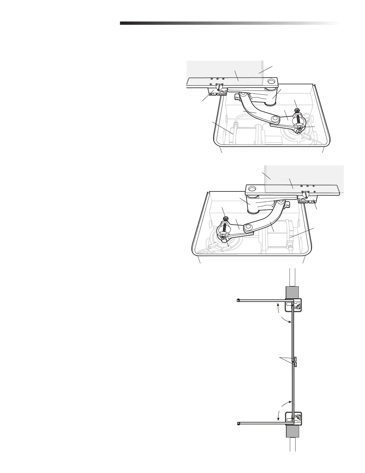
Figure 1: Left Hand Installation
Figure 1: Right Hand Installation
FASTEN THE GEARMOTOR AND ASSEMBLE THE OPERATOR
Gearmotor
Gate Arm
Manual Release
Curved Arm
Motor Arm
Nut
Bolt
(Gate in OPEN position)
Gate Bracket
Gearmotor
Gate Arm
Manual Release
Curved Arm
Motor Arm
Nut
Bolt
Gate Bracket
(Gate in OPEN position)

 Loading...