1.1 01/2012 © CAME cancelli automatici s.p.a. - The data and information in this manual may be changed at any time and without obligation on the part of Came Cancelli Automatici S.p.a. to notify said changes.
ENGLISH
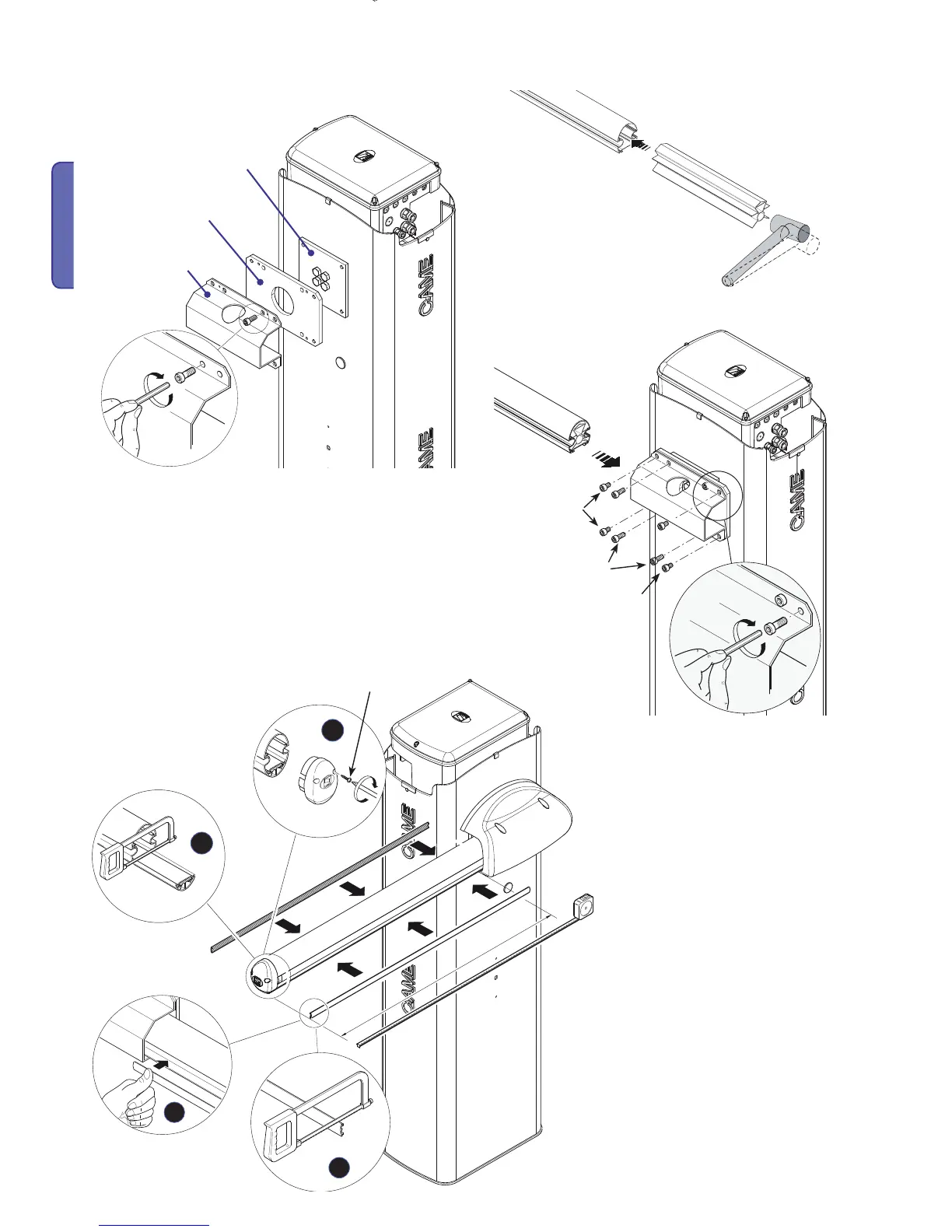
- Position the mid-plate and arm-attachment cover using just
one (M8x20) screw. Leave the creww loosened to facilitate
subsequent arm insertion.
Attachment plate
Mid plate
Arm-attachment cover
- Insert the arm into the attachment cover and fasten using the
M8x20 and M8x21 screws.
Note: if installing with the G03750 barrier arm, fi t the G03756
reinforcement.
- Cut the raceway cover profi les to the length
needed to insert them into the barrier arms’
raceway. Procedure to follow on both sides.
Finally fasten the arm end cap.

 Loading...


