1.1 01/2012 © CAME cancelli automatici s.p.a. - The data and information in this manual may be changed at any time and without obligation on the part of Came Cancelli Automatici S.p.a. to notify said changes.
ENGLISH
The following illustrations are just examples, in that the space for securing the operator and accessories depends on the overall
measurements. It is up to the installer to choose the most suited solution.
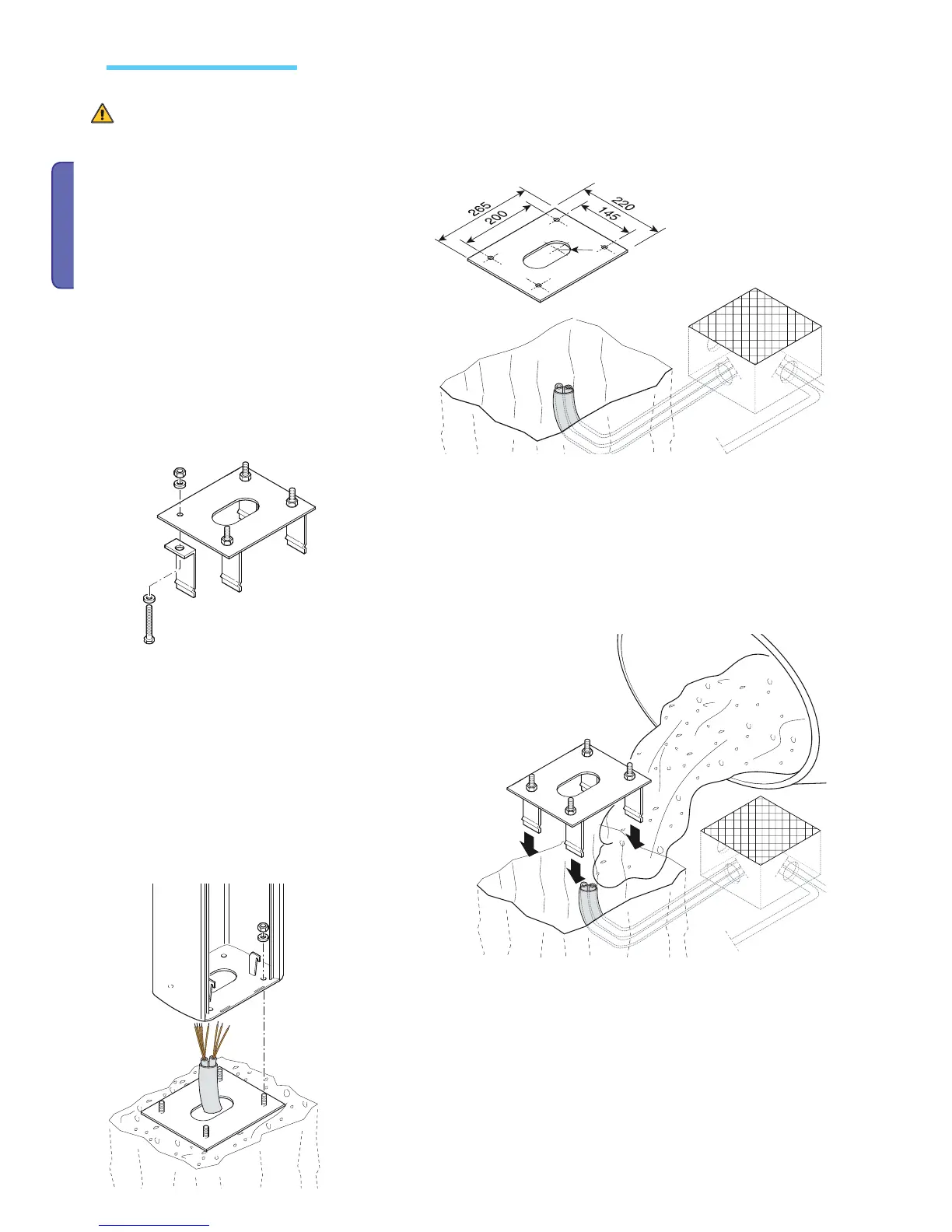
- PLATE.
- Dig a pit for the anchoring base and set up the required
corrugated tubes for the connections coming out of the
junction pit.
N.B. the number of tubes depends on the type of
installation and accessories used.
- Remove any protruding nuts or wahsers, position the cabinet onto the base and fasten
it.
Note: install the cabinet with the inspection door facing an easily accessible direction.
- Fill the pit with cement and sink the anchoring base (that is, the
plate + clamps) making sure the corrugated tubes pass throught
he hole set up on the plate and that they are not fi lled with cement.
The base must be perfectly level, clean and with the bolt threading
completely on the surface.
Wait at least 24 hrs for everything to solidify.
Preparing the automation base

 Loading...


