1.1 01/2012 © CAME cancelli automatici s.p.a. - The data and information in this manual may be changed at any time and without obligation on the part of Came Cancelli Automatici S.p.a. to notify said changes.
ENGLISH
Make sure you have all the tools and materials needed to carry out the installation in total safety and in accordance with current regula-
tions. The figure shows some examples of the tools needed by installers.
Before beginning to install, do the following:
• Check that installing the operator does not create any hazardous situations;
Set up a suitable omnipolar cut-off device, with distances greater than 3 mm between contacts, with sectioned
power source;
•
Check that any connections inside the container (made for continuity purposes of the protective circuit) be fitted with extra insulation
compared to other internal conductive parts;
• Set up proper conduits and electric cable raceways, making sure these are protected from any mechanical damage;
Installation must be carried by skilled, qualified technicians in accordance with current regulations.
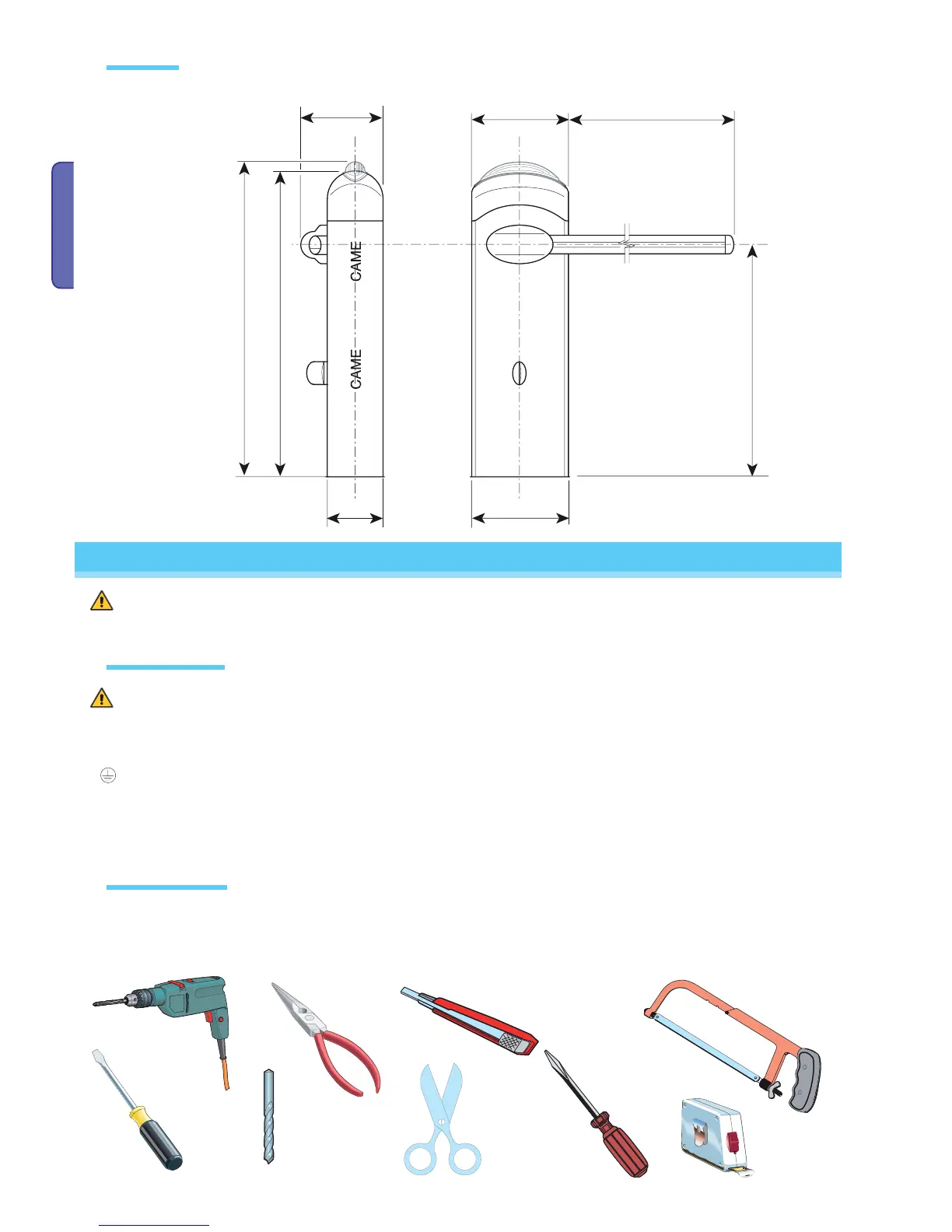
Measurements in mm
Installation
Dimensions
Preliminary checks
Tools and materials

 Loading...


