01/2012
© CAME cancelli automatici s.p.a. - The data and information in this manual may be changed at any time and without obligation on the part of Came Cancelli Automatici S.p.a. to notify said changes.
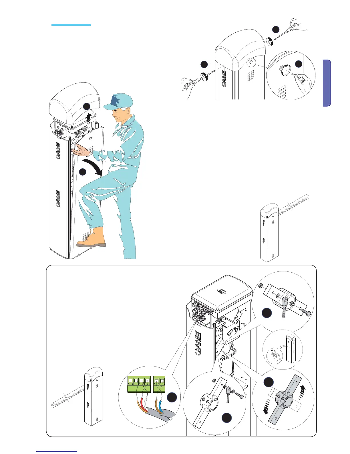
ENGLISH
- Remove the two top bolts from the upper dome, insert key into
lock and turn counter-clockwise.
- When installing on the right-hand side (DX), you need to invert
the barrier-arm's direction of opening, by doing the following:
- remove spring-hooking pin from the transmission arm (1);
- use key to release the gearmotor;
- turn the transmission arm (2);
- relock the gearmotor;
- Fit the anchoring pin into the hole opposite the initial one (3);
- invert the cables on terminals M and N, FA and FC (4).
- Lift up the dome and remove the cabinet hatch.
- the barrier is set up to be left-
hand (SX) installed.
Installing the unit

 Loading...


