01/2012
© CAME cancelli automatici s.p.a. - The data and information in this manual may be changed at any time and without obligation on the part of Came Cancelli Automatici S.p.a. to notify said changes.
ENGLISH
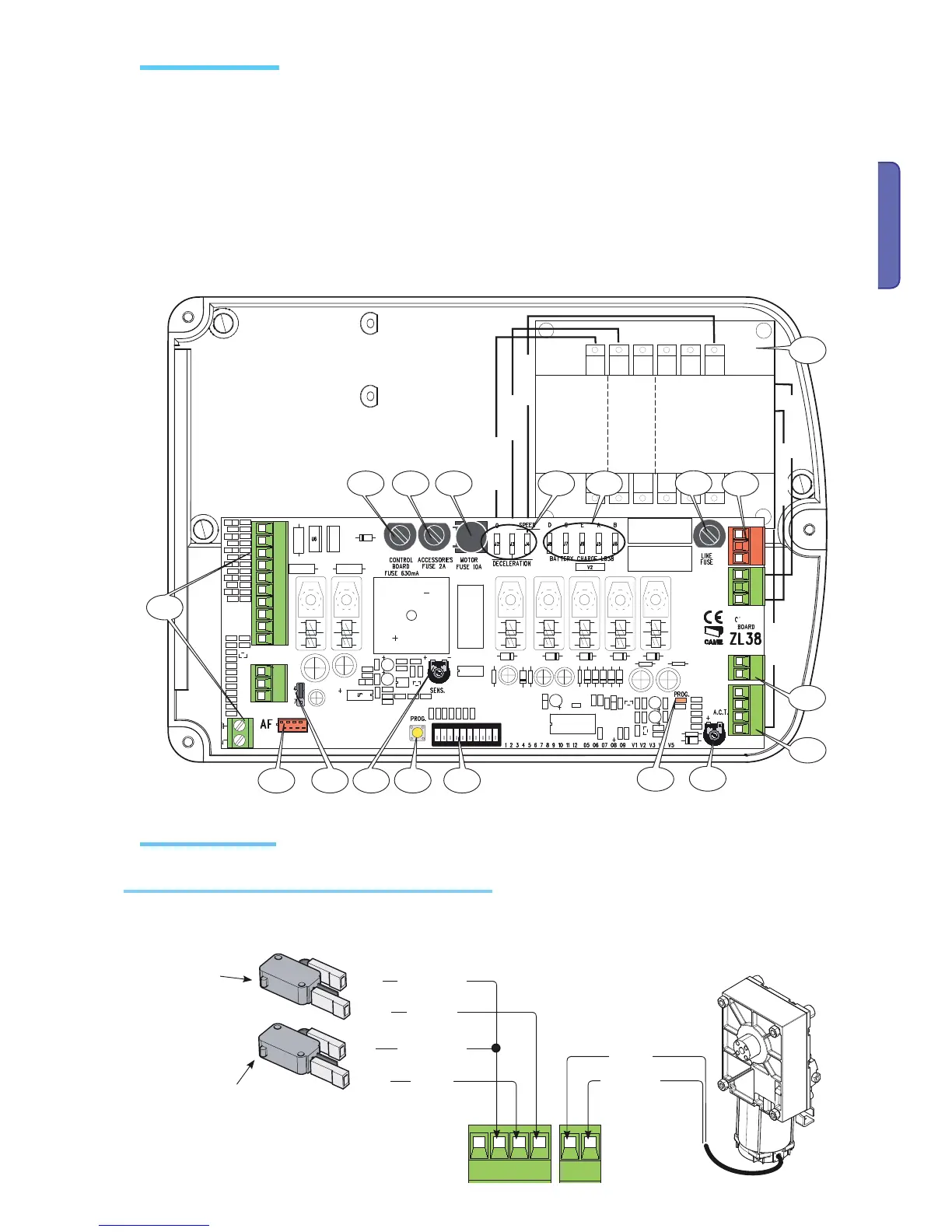
1- Accessories fuse
2 - Line fuse
3 - Line control unit
4 - Motor fuse
5 - Acessories terminals
6 - Radio-requency card socket (see table on p. 19)
7 - Trimmer SENS: adjusting amperometric sensitivity
8 - Trimmer TCA: adjusting automatic closing time
9 - Functions selection Dip switch"
10 - Code memorising button
11 - Warning LED for radio code/automatic closing
12 - Adjusting connectors for speed and slow-downs
13 - Connectors for connecting the (LB38) battery charger
14 - Selection jumper for command type for button on 2-7
15 - Transformer
16 - Power source terminals
17 - Motor terminals
18 - Limit switch terminals
Motor 24V (d.c.)
Gearmotor, limit switch
Closing microswitch
Orange
Orange
White
Red
Blue
Brown
Opening micro-
switch
Description of already required wiring connections. " For right-hand installation, see pge 7.
White
Red
Black
Brown
Blue
Brown
Main component parts
Electrical connections

 Loading...


