p. 3 - Manual FA 0 0 679- E N v. 1- 12/2017 - © CAME S.p.A. - The contents of this manual may be changed, at any time, and without notice.
GENERAL INSTALLATION INDICATIONS
⚠
Only skilled, qualifi ed sta must install this product.
⚠
Warning! Before working on the control panel, cut o the main power supply and, if present, remove any
batteries.
Preliminary checks
⚠
Before installing the control panel, do the following:
• make sure the fastening points and the anchoring surface are solid and protected from impacts. Only use
suitable nuts, bolts, dowels, and so on;
• set up a suitable dual pole cut o device along the power supply that is compliant with the installation rules. It
should completely cut o the power supply according to category III surcharge conditions;
• make sure that any connections inside the container (ones that ensure continuity to the protection circuit) are
fi tted with additional insulation with respect to those of other electrical parts inside:
• set up suitable tubes and conduits for the electric cables to pass through, making sure they are protected from
any mechanical damage.
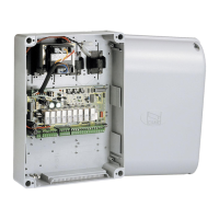
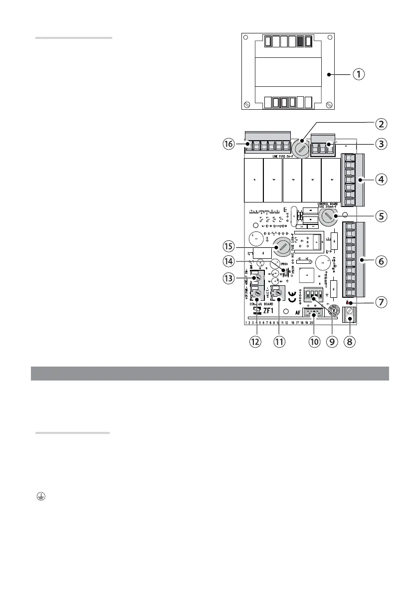
Description of parts
① Transformer
② Line fuse
③ Power supply terminals
④ Transformer terminal boards
⑤ Control-board fuse
⑥ Terminals for control and safety devices
⑦ Alert LED
⑧ Antenna terminal
⑨ DIP-SWITCH
⑩ AF card connector
⑪ Automatic closing trimmer
⑫ Operating time trimmer
⑬ Motor 2 delay trimmer
⑭ Programming key
⑮ Accessories fuse
⑯ Terminal board for microswitches
 Loading...