Do you have a question about the CAME ZF1N110 and is the answer not in the manual?
Critical safety advice, professional use declaration, and intended use.
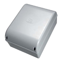
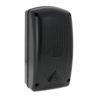
Overview of the control panel for swing gates and its specific application.
Key technical specifications including power, voltage, protection ratings, and dimensions.
Details on the line and control board fuses used in the unit.
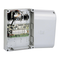
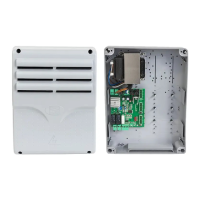
Identification and enumeration of all components on the control board.
Essential warnings before installation and required preliminary checks for safe setup.
Lists essential tools and materials needed for a safe and compliant installation.
Details on cable types and minimum thicknesses for various connections.
Instructions on how to securely mount the control panel using screws and dowels.
Guidance on connecting the main input voltage to the control panel.
Wiring diagrams for connecting two gearmotors with delay options.
Instructions for adjusting the motor torque using the faston positions.
Wiring for STOP button and OPEN-CLOSE-INVERT functions.
Details on connecting an electric lock, including voltage and power limits.
Information on connecting flashing lights and gate-open indicators.
Instructions for connecting photocells and handling unused inputs.
How the control board tests safety devices and required DIP-switch settings.
Description of functions controlled by DIP-switches like Auto-Closing and Safety Test.
Explanation of trimmer functions for Automatic Closing Time, Operating Time, and Motor Delay.
Steps for connecting the antenna and AF card before adding users.
Procedure for registering new users via the programming button and transmitter.
Steps to remove a specific user's access using DIP-switch and PROG button.
Procedure for erasing all registered users from the control panel memory.
Instructions for fitting and securing the control panel cover after connections.
Information on responsible dismantling and disposal of the product and its components.
| Brand | CAME |
|---|---|
| Model | ZF1N110 |
| Category | Control Panel |
| Language | English |