Do you have a question about the Canon 1180 and is the answer not in the manual?
Specifies the copier model series covered by this service information.
Indicates that the technical documentation has been revised to reflect functional modifications and corrections.
Details the key capabilities and advantages of the copier, such as high image quality and productivity.
Lists the detailed technical specifications of the copier, including physical dimensions, power requirements, and system components.
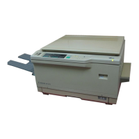
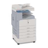
Provides an overview of the external parts of the copier, with diagrams and labels for identification.
Explains basic copier operations, including control panel usage and extended functions.
Describes the copier's overall functional construction, dividing it into major systems like exposure and image formation.
Details the operational sequence at power-on and during copying, illustrating component timing and states.
Explains the electrical control mechanisms for key motors and PCBs, including their functions and interconnections.
Outlines the basic operation of the exposure system, including the scanner, lamps, and sensors.
Details the scanner motor control circuit, explaining its functions for direction, speed, and reproduction ratio adjustments.
Explains the circuit controlling the scanning lamp's intensity, including on/off control, status detection, and voltage regulation.
Provides instructions for disassembling and assembling the copier's parts, emphasizing safety precautions.
Lists the main components of the image processing system, such as the CCD/CCD driver PCB and image processor PCB.
Details the specifications of the CCD unit and explains the function of the CCD driver circuit.
Describes the analog image processing steps, including signal matching and A/D conversion.
Covers various digital image processing techniques and the associated PCBs, such as shading correction and color conversion.
Provides instructions for disassembling and assembling the electrical parts of the image processing system, emphasizing safety precautions.
Details the major parts and functions of the laser exposure system, such as the laser semiconductor and scanner motor.
Explains the BD signal's role in synchronization and its generation process from the BD mirror.
Describes the circuit for controlling laser emission, intensity, and output switching, detailing signal functions.
Details the laser scanner motor's operation, speed control, and potential error conditions.
Provides instructions for disassembling and assembling the electrical parts of the laser exposure system, highlighting safety precautions.
Outlines the major functions of the image formation system, covering potential control and charging mechanisms.
Details the image stabilization mechanism's control items: grid bias, developing bias, and laser output.
Explains the control of the primary charging mechanism and grid bias, including operation and protection circuits.
Covers the control of developing assemblies, focusing on locking, toner concentration, and toner supply.
Describes the functions of the photosensitive drum cleaner assembly, including blade movement and waste toner collection.
Provides instructions for disassembling and assembling image formation system components, emphasizing safety.
Outlines the copier's pickup system, including paper sources and the center reference method for paper movement.
Details the arrangement of rollers and sensors for the pickup assembly across different copier models.
Describes the basic construction of the duplexing unit, including its capacity, motors, and related error codes.
Explains the control of registration and attraction mechanisms, including roller movement and motor drives.
Details the components of the transfer drum and their functions, including motors, sensors, and solenoids.
Lists the sensors used to monitor paper presence, absence, and movement for jam detection.
Provides instructions for disassembling and assembling the pickup assembly components, emphasizing safety precautions.
Details disassembly and assembly procedures for transfer and delivery assemblies, including safety warnings.
Outlines the major functions of the fixing unit, including its drive system, heaters, cleaning mechanisms, and oil application.
Explains how the copier controls the fixing roller speed using drive signals and speed switch signals.
Details fixing temperature control via heaters, thermistors, and thermal switches, including protective functions.
Provides instructions for disassembling and assembling fixing system components, emphasizing safety.
Describes the control panel's functional construction, including PCBs, LCD, and key operations.
Explains firmware updating methods using DIMMs or the Service Support Tool (SST) for the machine's CPU PCB.
Details the copier's counters that track copy numbers based on paper type, function, color, and size.
Lists the names, functions, and error codes of the 14 fan motors used to prevent overheating.
Explains DC power supply via the DC power supply PCB and its distribution to loads through switches.
Describes the copier's editor function, which uses a tablet and pen switch for input and area selection.
Provides general instructions for disassembling and assembling copier parts, emphasizing safety precautions.
Outlines the paper deck's capabilities, including its capacity, construction, and paper size settings.
Explains how the side paper deck uses sensors to monitor paper movement and detect jams, providing removal instructions.
Provides instructions for disassembling and assembling paper deck components, emphasizing safety precautions.
Details requirements for the installation site, including power, temperature, humidity, and floor level.
Instructions for unpacking the copier, removing protective materials, and safe handling.
Procedures for relocating the copier, including removing options and securing components for transport.
Details how to attach the document holder to the copier's right and left sides using stepped screws.
Provides step-by-step instructions for mounting the control card unit, including disconnecting connectors and attaching the insulating sheet.
Guidance on installing the Copy Data Controller-A1, referencing a separate installation procedure.
Details the installation procedure for the remote diagnostic device, including required tools and safety.
Provides instructions for installing the cassette heater, including checking parts and making connections.
Lists parts that require periodic replacement, their part numbers, quantity, expected life in copies, and remarks.
Details consumable and durable parts for the copier and paper deck, including part numbers and life expectancy.
Outlines scheduled servicing tasks, checks, and remarks, typically performed every 20,000 copies.
Provides a detailed list of scheduled servicing tasks for copier and paper deck components.
Explains basic image adjustment, density checking, color balance, and test print procedures.
Lists standards and adjustments for image, exposure, image formation, pickup, fixing, and external systems.
Provides initial checks for common image faults like light copies, uneven density, fogging, and white lines.
Lists various error codes (E000 to E804) with their corresponding causes and timing of detection for troubleshooting.
Details common paper jam locations and troubleshooting steps for feeding issues like double feeding and wrinkles.
Identifies electrical components like sensors, thermistors, lamps, clutches, solenoids, motors, and PCBs.
Explains the service mode structure: initial, Level 1/2, and Level 3 screens.
Details the self-diagnostic mechanism for checking machine states and indicating fault codes on the control panel.
Provides a detailed timing chart illustrating the sequence of operations for various components during copying.
Lists important signals and their abbreviations used throughout the manual for clear communication.
Presents a comprehensive circuit diagram showing the interconnections between various assemblies and PCBs.
Illustrates the general circuit diagram specifically for the paper deck assembly, showing component connections.
Lists special tools required for servicing the copier, including their part numbers, shapes, ranks, and remarks.
Details the recommended solvents and oils for cleaning and lubricating various copier parts, along with their composition and remarks.
| Print Resolution | 600 x 600 dpi |
|---|---|
| Maximum Copy Resolution | 600 x 600 dpi |
| Maximum Copy Paper Size | A4 |
| Type | Laser |
| Paper Capacity | 250 sheets |
| Connectivity | USB 2.0 |
| Duplex Printing | No |
| Warm-up Time | Less than 10 seconds |