CHAPTER 9 EXTERNALS / AUXILIARY MECHANISMS
9-30
COPYRIGHT
©
2002 CANON INC. CANON CLC1100/1130/1150/1160/1180 REV.2 DEC. 2000 PRINTED IN JAPAN (IMPRIME AU JAPON)
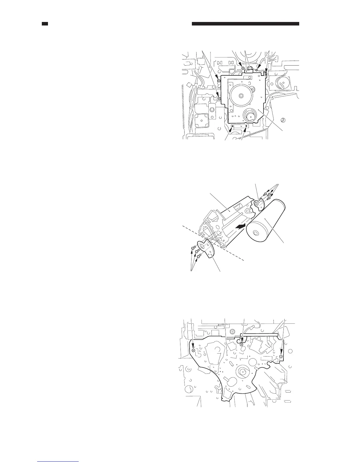
11) Remove the static eliminator brush.
12) Disconnect the two connectors [12], and
remove the seven screws [13]; then,
detach the drum motor assembly [14]
together with the fixing plate.
13) Remove the four screws, and detach the
drum motor from the mounting plate.
Figure 9-730
2. Mounting the Drum Motor
Assembly
When the drum motor assembly is
removed from the copier, be sure to adjust its
position using the drum shaft position tool
(FY9-3045) when mounting it back to
eliminate any discrepancy.
1) Slide out the photosensitive drum unit
from the copier.
2) Remove the six screws [1], and detach the
photosensitive drum butting block [2]
(front, rear); then, detach the
photosensitive drum [3] from the
photosensitive drum frame unit [4].
Figure 9-731
3) Insert the photosensitive drum frame unit
[5] in the copier, and mount it with three
screws [6].
Figure 9-732
[13] [12] [13][13]
[13]
[14]
[13]
[2] [1]
[3]
[4]
[1] [2]
[6][6][5][6]
 Loading...