COPYRIGHT
©
2002 CANON INC. CANON CLC1100/1130/1150/1160/1180 REV.2 FEB. 2002 PRINTED IN JAPAN (IMPRIME AU JAPON)
6-7
CHAPTER 6 IMAGE FORMATION SYSTEM
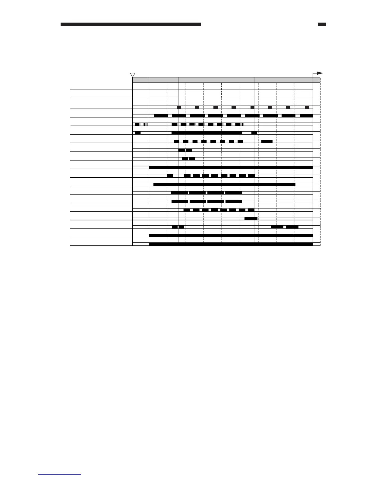
C. Sequence of Operations (image formation system)
Figure 6-104 A4/LTR, 2 Copies, Full Color, Direct, Cassette 1
1 2 3 4 5 6 7 8
Side A sensor (PS2)
Side B sensor (PS3)
Photosensitive drum revolution
Transfer drum revolution
Pre-registration paper sensor
(PS30)
Laser
Scanner motor (PM15)
Scanning lamp (LA2)
Post-cleaning high-voltage
output
Pre-exposure lamp (LA1)
Developing bias DC component
Primary high-voltage output
Transfer high-voltage output
Developing bias AC component
External/internal static eliminator
high-voltage output
Separation high-voltage output
Drum motor (M2)
Main motor (M4)
Attraction high-voltage output
DSRDY
ended
INTR COPY LSTR
STBY
DSRDY
YMM CC Y KK
MC Y K
MC Y K
Y
M
M
C
C
Y
KK
[2]
[1]
[1] Shading correction [2] Potential control measurement