COPYRIGHT
©
2002 CANON INC. CANON CLC1100/1130/1150/1160/1180 REV.1 JAN. 2000 PRINTED IN JAPAN (IMPRIME AU JAPON)
9-23
CHAPTER 9 EXTERNALS / AUXILIARY MECHANISMS
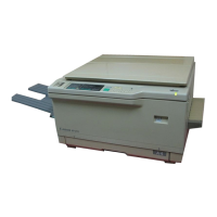
3) Disconnect the connector [3], and remove
the four screws [4]; then, detach the LCD
PCB.
Figure 9-713
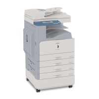
4. Removing the Numeric Keypad
PCB
1) Remove the control panel PCB.
2) Remove the control panel fixing plate.
3) Remove the 13 screws [1], and remove the
pilot lamp assembly [2].
4) Remove the numeric keypad PCB [3].
Figure 9-714
 Loading...