CHAPTER 2 BASIC OPERATION
2-10
COPYRIGHT
©
2002 CANON INC. CANON CLC1100/1130/1150/1160/1180 REV.0 MAR. 1999 PRINTED IN JAPAN (IMPRIME AU JAPON)
III. CONTROLLING ELECTRICAL MECHANISMS
A. Controlling the Main Motor (M4)
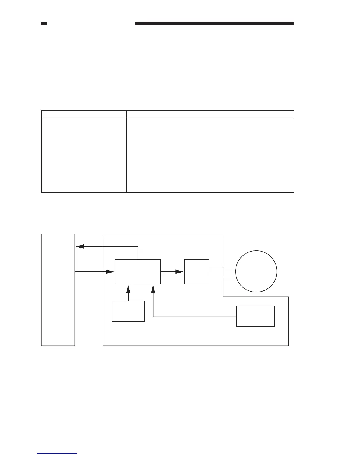
1. Outline
Table 2-301 shows the functions of the main motor control circuit, and Figure 2-301 shows a
block diagram of circuit.
Item Description
Power supply 38 VDC from the DC power supply PCB.
Drive signal Drive signal (MNMON) from the DC driver PCB.
Moving/drive parts Registration roller, attraction roller, developing assembly,
multifeeder feed roller.
Control Turing on/off the main motor.
Controlling the main motor to a constant speed.
Detects errors.
Table 2-301
Figure 2-301
M4
DC driver
PCB
MNMRDY
MNMON
Main motor (M4) driver PCB
Main motor
Rotation speed
control circuit
Reference
pulse
generation
Motor
driver
Rotation speed
detection
 Loading...