DC10 E, DC20 E
DISASSEMBLING
13
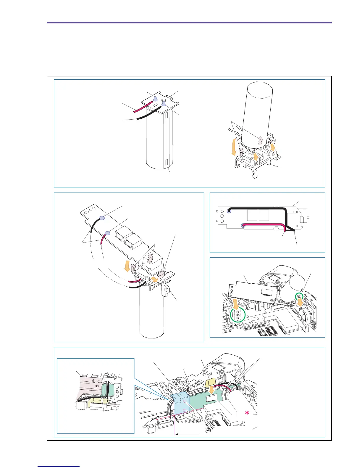
<Note on Reassembling>
(1) Attach the Main Capacitor, the Condenser Wire, and the Flash PCB Holder as shown in the figure below.
(2) Attach the FLASH PCB and the Condenser Wire as shown in the figure below.
(3) Treat the Condenser Wire as shown in the figure below.
(4) Attach the Flash PCB Ass'y with its dowels aligned.
(5) Attach the FLASH FPC, the Condenser Wire, the Flash Cable, and the UL Tape as shown in the figure below.
Fig. 10
Note on Reassembling (1)
Note on Reassembling (2) Note on Reassembling (3)
Note on Reassembling (4)
Note on Reassembling (5)
Solder β
([−] terminal)
Solder α
([−] terminal)
Solder α
([+] terminal)
Solder β ([+] terminal)
Condenser Wire +
(Red)
Condenser Wire + (Red)
Condenser Wire −
(Black)
Condenser
Wire
Solder the Condenser Wire to
the Flash PCB Ass'y and insert
it to the Flash PCB Holder.
Be careful about the polarity
of the Condernser wire at the
soldered section α.
Condenser Wire − (Black)
Main Capacitor
(White line side on cylinder is negative [−])
Be careful about the polarity of
the Capacitor and Condenser
Wires at the soldered section β.
Insert into the Flash PCB Holder.
FLASH PCB
Push into
the Claws.
1.Insert under the rib.
Claws
Insert into
the hole.
Flash PCB
Holder
Flash PCB
Holder
2.Push into the Claws.
Claws
Dowel
Dowel
Flash PCB Ass'y
CAPACITOR PCB
Insert the FLASH FPC
so that it wraps the Flash
Cable and Condenser
Wire. Be sure to stick UL
Tape so that it covers the
discharge pad.
And fix Flash Cable at the
same time.
Solder the Capacitor and
Condenser wire to the Condenser
PCB.
UL Tape
(9 × 20mm)
Flash Cable
Flash Cable
ST Wire
Protector
FLASH FPC
Condenser Wire
Take care not to extend onto
the Lens Holder.
Lens
Holder
CN500
Discharge pad
Attachment
reference
Attachment
reference