LASER CLASS 730i/720i/710 Chapter 4: Maintenance and Service
4-18
4.2.3 Error codes
a) Service error code output
When service data #1 SSSW SW01 bit 0 is set to “1” then service error codes are printed on
the activity management reports, reception result reports and error transmission reports
when communication is terminated due to an error. Also, the following is displayed when
an error occurs.
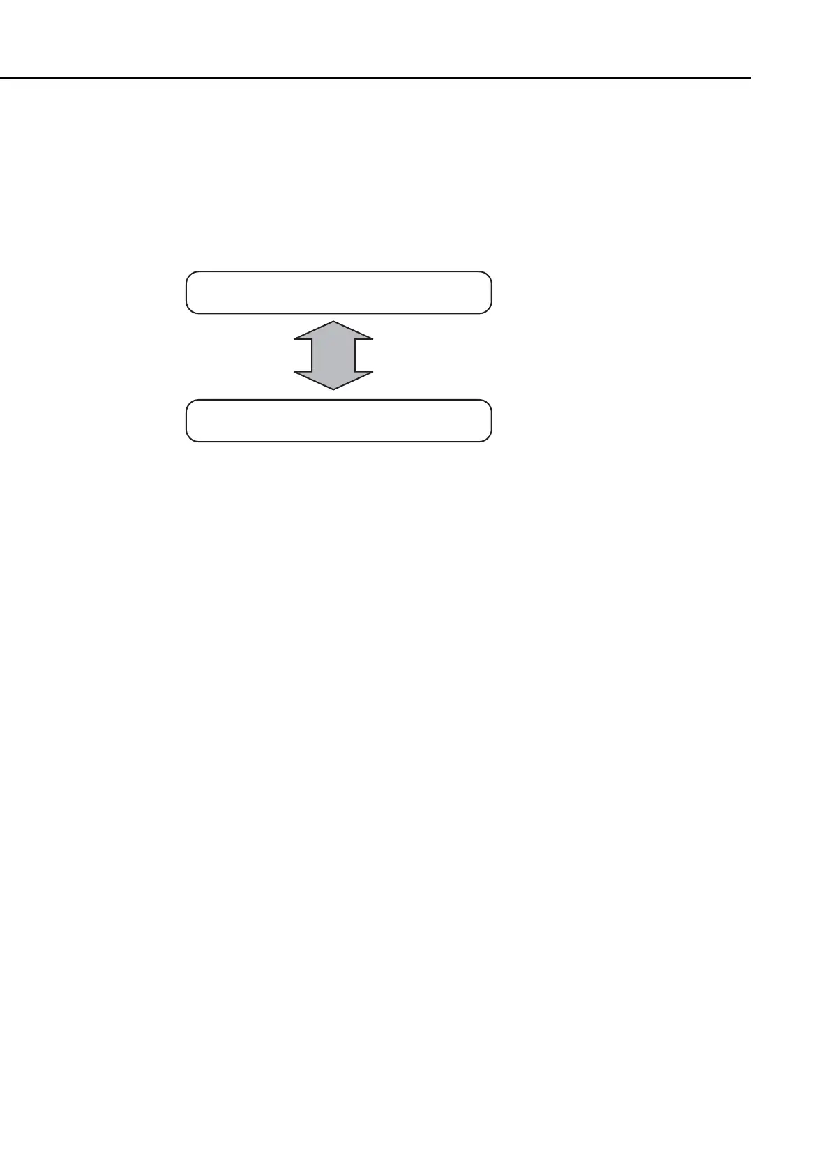
Figure 4-8 Service Error Code Display
b) Error code countermeasures
The following item c) lists all the error codes that the product can display. As for causes and
countermeasures, only the error codes which are newly incorporated in the unit as well as
which require remedies unique to the product are included in the item d). For the causes and
countermeasures of other error codes, refer to the separate
G3/G4 Facsimile Error Code
List (Rev. 2)
.
• Increase the transmission level
Increase service data #2 MENU Parameter No.07 toward 0 (dBm).
• Decrease the transmission level
Decrease service data #2 MENU Parameter No.07 toward -15 (dBm).
• Echo measures
Change the following bit switches of service data #1 SSSW SW03.
Bit 4: 1 Ignore the first DIS signal sent by the other fax machine.
0 Do not ignore the first DIS signal sent by the other fax machine.
Bit 5: 1 Transmit a tonal signal (1850 or 1650 Hz) when the other fax machine
sends a DIS signal.
0 Do not transmit a tonal signal when the other fax machine sends a DIS
signal.
Bit 6: 1 Transmit a 1850-Hz tonal signal when bit 5 is 1.
0 Transmit a 1650-Hz tonal signal when bit 5 is 1.
Bit 7: 1 Transmit a tonal signal before sending a CED signal.
0 Do not transmit a tonal signal before sending a CED signal.
Display alternates repaetedly
TX/RX No. 5001
START AGAIN ##0106