Do you have a question about the Canon LASER CLASS 710 and is the answer not in the manual?
Explains product specifications and how to service the unit safely.
Explains the technical theory of the product.
Explains the assembly and disassembly of the product.
Explains how to maintain products for adjustment and troubleshooting.
Explains the information of optional products and user data flow.
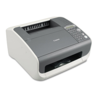
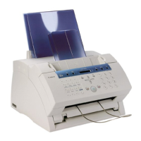
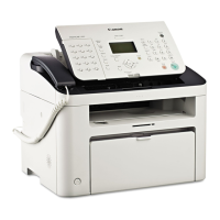
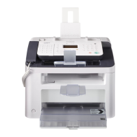
Provides an overview of the product's features and specifications.
Details the G3 facsimile transceiver's compliance with ITU-T standards.
Lists type, body color, power source, usage environment, noise, dimensions, and weight.
Details applicable lines, transmission method, protocols, modulation, speed, coding, error correction, and protocols.
Covers type, sheet dimensions, ADF capacity, effective scanning width, method, and density.
Details paper dimensions, cassette capacity, tray stacking, printing method, and cartridge.
Covers copy resolution, multiple copy, color copy, magnification ratio, and zoom.
Details functions like polling, confidential reception, and auto dialing.
Presents a diagram of the machine's front view with numbered components.
Lists optional features like Dual-line Upgrade Kit, Feeders, Handset Kit, Memory, and Stamp Unit.
Provides guidelines for handling and storing toner cartridges.
Explains how to load paper into cassettes, recommended paper, and size settings.
Provides detailed technical information about the machine's components and systems.
Illustrates the mechanical layout of the machine's main assemblies.
Explains the function and components of the scanner section.
Details the function of various parts within the scanner mechanism.
Explains the function of the paper supply section.
Explains how the cassette feeder drives the pick-up roller via the main motor.
Explains how paper size errors occur and how they are indicated.
Describes detection and retry control for various paper pickup jam types.
Describes the main sections of the LASER beam printer engine.
Details the components and function of the Laser/Scanner unit.
Explains the toner sensor and detection mechanism.
Details the transfer charging roller and static eliminator.
Describes the fixing assembly and pressure roller, and its on-demand method.
Lists various fixing heater malfunctions detected by the printer controller.
Explains the twin beam method for high-resolution printing without speed loss.
Provides instructions for disassembling and assembling machine components.
Details safety precautions for electrical shock, high temperature, battery replacement, fire, ignition, and movable parts.
Warns about ESD damage to components and provides countermeasures.
Warns about permanent eye damage from laser light and prohibits unit disassembly.
Explains the All Clear operation to reset values and settings to defaults.
Provides step-by-step guides for disassembling various machine components.
Step-by-step guide to disassembling the lower document separation roller.
Step-by-step guide to disassembling the upper document separation roller.
Procedure for disassembling the multi-purpose paper pick-up roller and separation pad.
Procedure for disassembling the main unit's paper pick-up roller.
Procedure for disassembling the feeder's paper pick-up roller.
Procedure for detaching the separation pad from the cassette.
Step-by-step guide to disassembling the fixing assembly.
Covers procedures for maintaining and servicing the machine's components.
Lists consumables like toner cartridge and stamp ink and when to replace them.
Details locations and conditions for cleaning various parts of the machine.
Lists parts with a defined replacement life based on sheets processed.
Lists adjustment items, specifically checking the pressure roller nip width.
Lists general tools required for servicing and their uses.
Lists special tools required for servicing, including part numbers.
Provides instructions for cleaning various parts of the machine.
Instructions for cleaning the transfer guide, including wiping dust and toner.
Provides procedures to check the fixing unit's pressure roller nip width.
An index to help identify problems and find corresponding countermeasures and pages.
Lists user error messages, their causes, and solutions.
Lists printer error messages, their causes, and solutions.
Lists error codes and provides countermeasures, referring to external documents for others.
Covers errors not displayed, like unit not turning on or abnormal display.
Details troubleshooting for printing issues like paper feed and abnormal printing.
Troubleshooting for faulty scanning where print is good but copy is poor.
Troubleshooting for issues with the LCD panel, LED lamps, and operation panel keys.
Guides to narrow down the cause of communication problems.
Details procedures for analyzing and resolving communication issues.
Describes hardware switches and service data settings.
Diagram showing the structure and default settings of service data switches (#1 SSSW).
Explains how to read and interpret bit switch tables for service settings.
Contains supplementary information such as installation, user data, options, and technical details.
Guides the user through selecting a site, unpacking, making connections, and setting paper and line types.
Describes how to check reading/printing quality and conduct a communications test.
Provides instructions for safely moving the fax machine, including lifting procedures.
Diagram illustrating the flow for setting user data via the operation panel.
Provides steps for registering and setting printer parameters via the menu.
Diagram illustrating the flow of the printer setting menu options.
Details adding memory boards for fax receiving or printer images.
Warns about electrostatic discharge when handling memory boards.
Provides diagrams and steps for installing memory boards.
Provides installation and troubleshooting for the handset kit.
Provides installation and operation verification for the stamp unit.
Provides safety, installation, and troubleshooting for the FXL-Cassette Feeder 6.
Provides safety, installation, and troubleshooting for the FXL-Cassette Feeder 7.
Provides safety, installation, and troubleshooting for the Dual-line Upgrade Kit III.
Provides safety, installation, and troubleshooting for the Printer Kit III.
Provides safety, installation, and troubleshooting for the Network Kit III.
Explains the manual's structure, parts list conventions, tools, lubrication, replacement guides, and indexes.
Lists parts layout illustrations by illustration number for easy identification.
Guides to find parts using illustrations, key numbers, and part lists.
Lists tools used for servicing products.
Identifies parts requiring lubrication for smooth operation and conductivity.
Explains special care and cautions for parts replacement.
| Type | Laser Fax Machine |
|---|---|
| Resolution | 600 x 600 dpi |
| Memory | 512 KB |
| Fax Modem Speed | 33.6 Kbps |
| Paper Capacity | 250 sheets |
| Compatibility | Windows, Mac |
| Transmission Speed | 3 seconds per page |
| Automatic Document Feeder (ADF) | Yes |
| Printing Method | Laser |
| Print Speed | 8 ppm |