LASER CLASS 730i/720i/710 Chapter 5: Appendix
5-61
(7) Fasten the shield plate in place with the seven screws. (eight screws for LASER
CLASS 730i/720i)
(8) Fasten the right cover in place with the two screws.
(9) Connect the modular cord (telephone line) to the fax (L1 jack).
(10) Connect the included modular cord to the fax (L2 jack).
(11) Connect the power supply cord to the fax.
b-5) Check after the Kit Installation
After installing the kit, carry out the following procedure to ensure that the kit is properly
identified by the fax.
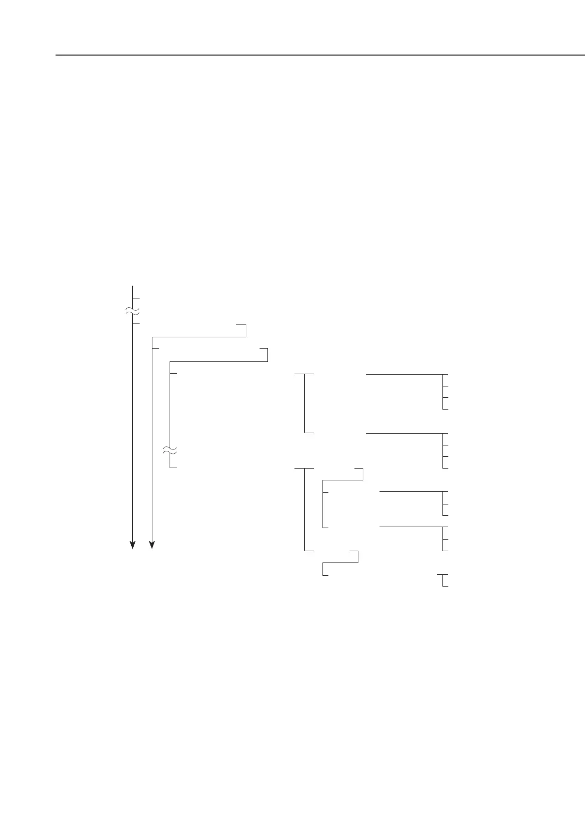
(1) Referring to the flow chart, enter user data registration; then check the following menu.
Figure 5-70 Menu Check
(2) After confirming this, push the Stop button, which will put the machine into a standby
condition.
(3) If the menu is not displayed, return to
b-4) Attaching to the main unit
, re-attach the
kit, and then re-check with user data registration.
b-6) Removing the kit
When removing the kit, perform the steps in
b-4) Attaching to the main unit
in reverse
order. Be sure to remove the kit only after turning the power off.
1. TEL LINE SETTINGS
8.TX LINE SELECTION
1. LINE 1
2.LINE 2
AUTO
1. LINE 1
2. LINE 2
MAN.
1. DEFAULT TEL LINE
1.USER TEL NO.
2.TEL LINE TYPE
3.TX START SPEED
4.RX START SPEED
1.USER TEL NO.
2.TEL LINE TYPE
3.TX START SPEED
4.RX START SPEED
PRIMARY
SECONDARY
PROHIBIT TX
PRIMARY
SECONDARY
PROHIBIT TX
LINE 1
LINE 2
3. FAX SETTINGS
1. PAPER SETTINGS
Data Registration
1. USER SETTINGS