14
MLB242
User’s Guide MLB242-V1
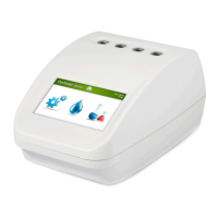
1.3 The MLB242 analyzer
Ports at back site for power supply and data transfers.
4 Reading cells, with dierent wavelengths.
Operating cell is indicated by a blue shining control LED.
Cells not used for testing can be used for incubation pur-
poses.
Power ON: press button short
Power OFF: press button for 3 seconds
4,3” TFT-Colour Display with touch-function.
Figure 1 MLB242 Modules
TOUCH function: is an active area on display expressed as a symbol that can be used
to carry out a function.
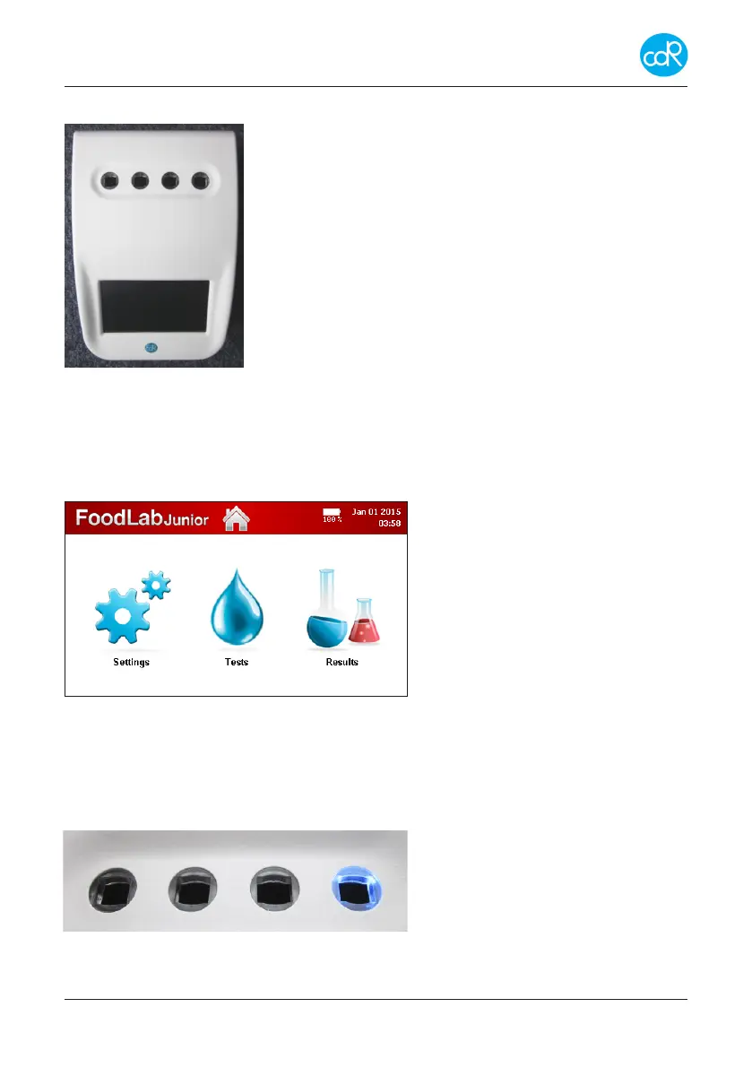
Operating parts
Colour touchscreen display
Top line with:
Analyzer name, HOME button
Optional: Battery loading status.
Date/Time
Main part
Menus for Settings, Tests
And Results (DATABASE)
Figure 2 Main Dialogue
Measuring cells
After test selection a blue illuminated LED shows the reading cell that must be used for
chosen test. Automatically the cell will be checked, if it fails the operator will be warned
and the specic test is inhibited for further use. As a new innovation every measuring
cell is equipped with an Insertion Tube Sensor at the button to control whether a cell
is occupied by a cuvette or not. (see
chapter 3.7.10)
During reading don’t touch cuvette or
other parts and avoid any vibrations!
Figure 3 Measuring cells