kVent – rel 3.1 – 22/06/2018
9
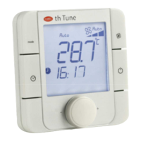
2.4 Input/Output
In/Out
Label
Type
kVent
Universal I/O In U NTC input 10
In U PT1000 input 10
In U PTC input 10
In U PT500 input 10
In U PT100 input 5
In U
0 to 1 Vdc/0 to 10 Vdc input
(powered by controller)
0
In U
0 to 1 Vdc/0 to 10 Vdc input
(external power supply)
10
In U
0 to 20 / 4 to 20mA input
(powered by controller)
2
In U
0 to 20 / 4 to 20mA input
(powered externally)
4
In U
0 to 5 V input for ratiometric
probe (+5Vref)
2
In U
Digital input w/ voltage-free
contact
10
In U Fast digital inputs 2
Out U
0 to 10 Vdc output, not
opticallyisolated
5
Out U
PWM output, not optically-
isolated
10
TOTAL UNIVERSAL 10
Digital inputs In DI Voltage-free contacts 2
TOTAL DIGITAL INPUTS 2
Analog
outputs
Out Y
0 to 10 Vdc output, not
opticallyisolated
2
Analog
outputs
Out Y
PWM output, not optically-
isolated
2
Analog
outputs
Out Y
Output for single-pole
stepper motor
1
TOTAL ANALOG OUTPUTS 2
Digital outputs Out NO/NC relay output 1
Out NO relay output 5
TOTAL DIGITAL OUTPUTS 6
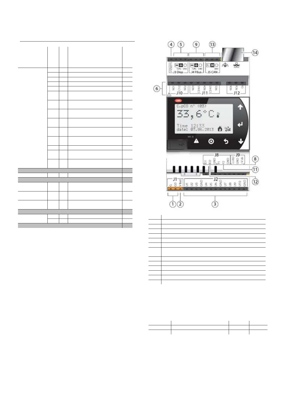
Connections terminals
2.4.1
1 Power connector G(+), G0(-)
2 Vbat: terminal for external Ultracap module (accessory)
3 Universal inputs/outputs
4 +Vterm: terminal power supply
5 Terminal connector
6 Relay digital outputs
8 +5VREF: power supply for ratiometric probes
+VDC: power supply for active probes
9 FieldBus connector
10 BMS connector
11 Analogue outputs
12 Digital inputs
13 CANbus connector
14 Ethernet port
thTune addressing
2.4.2
thTune communicates with the controller throu ModBus network,
so the slave devices must have different ModBus address.
To configure ModBus address of thTune, press buttons
FAN+ON/OFF for 3s, then enter password 22. Parameters are:
Addr ModBus address 1 1
bAud Baudrate 2 2