15
ENG
pCO5plus +0300020EN rel. 1.2 - 07.11.2013
4. INSTALLATION
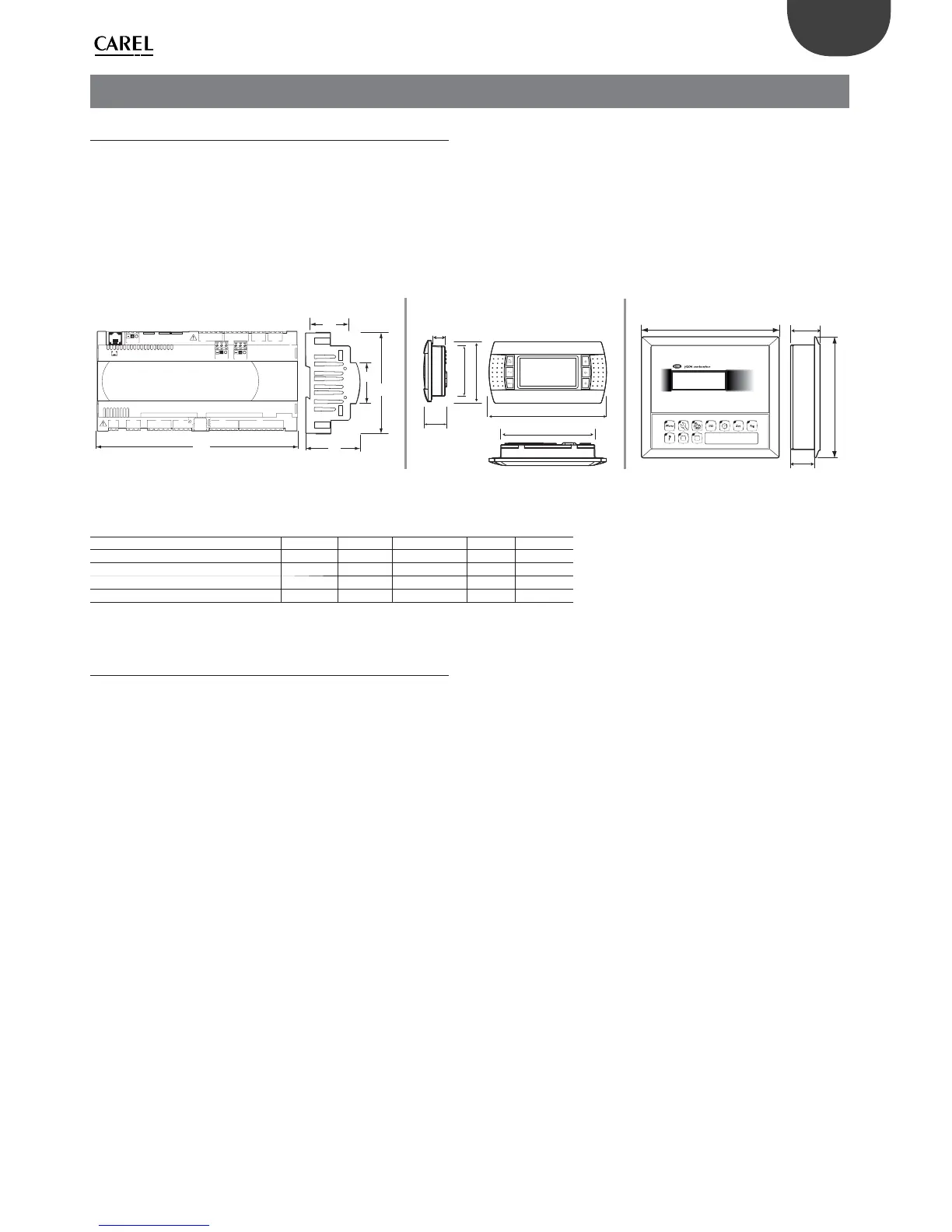
4.1 Mounting on DIN rail and dimensions
The controller is designed to be mounted on a DIN rail. The fi gure below
shows the dimensions for each size.
Mounting:
• place the controller on the DIN rail and press it down gently. The tabs
at the back will snap into place and lock the controller.
Removing:
• lift the tabs using a screwdriver applied to their release slots. The tabs
are kept in place by springs.
pCO5+
pGDE
pGD1*
A
110
45
B
44
156
125
67
18
30
82
202
53
43
177
Fig. 4.a
DIMENSIONS (mm)
Small Medium Buit-in driver Large Extralarge
A 227,5 315 315 315 315
B 60 60 60 60 60
B - with USB port/built-in terminal
70 70 70 70 70
B - with ULTRACAP module
-- 75 --
Tab. 4.a
4.2 Installation
Environmental conditions
Avoid installing the controller and the terminal in places with:
• exposure to direct sunlight and to the elements in general;
• temperature and humidity outside the product’s range of operation
(see “Technical Specifi cations”);
• large, rapid fl uctuations in room temperature;
• strong magnetic and/or radio frequency interference (avoid installing
near transmitting antennas);
• strong vibrations or knocks;
• presence of explosives or fl ammable gas mixtures;
• exposure to aggressive and polluting atmospheres (e.g. sulphur and
ammonia vapours, salt mist, fumes) that can cause corrosion and/or
oxidation;
• exposure to dust (formation of a corrosive patina with possible
oxidation and reduced insulation);
• exposure to water.
Positioning the controller inside the electrical panel
Install the controller inside an electrical panel in a position where it cannot
be reached and is protected from knocks or impacts. The controller should
be placed inside the panel in a position where it is physically separated
from power components (solenoids, contactors, actuators, inverters,
etc.) and their respective cables. The ideal solution is to house these two
circuits in two separate cabinets. Proximity to such devices/cables may
cause random malfunctions that are not immediately evident. The panel’s
casing must allow an adequate fl ow of cooling air.