46
ENG
pCO5plus +0300020EN rel. 1.2 - 07.11.2013
8. TECHNICAL SPECIFICATIONS
8.1 pCO5+ Technical Specifi cations
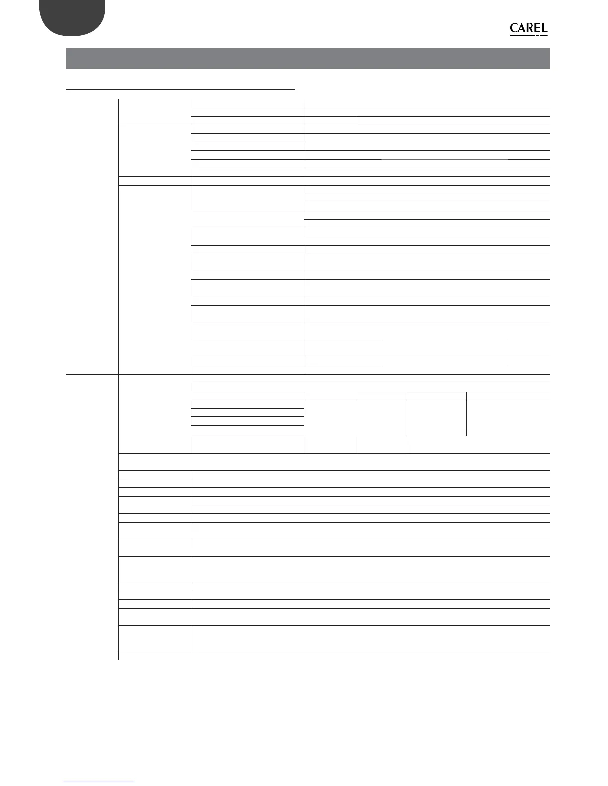
Physical specifi -
cations
Dimensions
SMALL 13 DIN modules 110 X 227,5 X 60 mm
MEDIUM, LARGE, EXTRALARGE 18 DIN modules 110 X 315 X 60 mm
BUILT-IN DRIVER 18 DIN modules 110 X 315 X 75 mm
Plastic case
Mounting Can be mounted on DIN rail in accordance with DIN 43880 and IEC EN 50022
Material Technopolymer
Flame retardancy V2 (standard UL94) and 850 °C (standard IEC 60695)
Temperature for the ball pressure test 125 °C
Creeping current resistance ≥ 250 V
Colour White RAL 9016
Built-in terminal PGD1 (132x64 pixel) with backlit keypad
Other characteristics
Operating conditions
P+(3, 5)*******0** (no built-in terminal): -40T70 °C, 90% RH non-condensing(*)
P+(3, 5)*******E** (with built-in terminal): -20T60 °C, 90% RH non-condensing
(*) with Ultracap module installed: -40T60°C
Storage conditions
P+(3, 5)*******0** (no built-in terminal): -40T70 °C, 90% RH non-condensing
P+(3, 5)*******E**(with built-in terminal): -30T70 °C, 90% RH non-condensing
Protection rating
Models with USB port and/or Ultracap module: IP20 (front panel only)
Models without USB port and without Ultracap module: IP40 (front panel only)
Control pollution situation 2
Class of protection against electric
shocks
to be integrated into Class I and/or II units (on versions without valve driver), and
Class I units (on versions with valve driver)
PTI of insulating materials PCB: PTI 250 V; insulating material: PTI 175
Period of electrical stress across
insulating parts
long
Type of action 1C; 1Y in SSR versions
Type of disconnection or
microswitching
microswitching
Category of resistance to heat and
fi r e
Category D (UL94-V2)
Ageing characteristics (operating
hours)
80.000
No. of automatic operating cycles 100.000 (EN 60730-1); 30.000 (UL60730)
Rated impulse voltage 2500V
Electrical speci-
fi cations
Power supply
SMALL, MEDIUM, LARGE, EXTRALARGE: Use a dedicated, class 2, 50 VA safety isolating transformer
BUILT IN DRIVER: Use a dedicated, class II, 100 VA safety isolating transformer
Vac P (Vac) Vdc P (Vdc)
SMALL
24 Vac (+10/-
15%), 50/60 Hz
to be protected
by 2.5 A T
external fuse
45 VA
28 to 36 Vdc
(-20/+10%) to be
protected by 2.5 A
T external fuse
30 W
MEDIUM
LARGE
EXTRALARGE
BUILT-IN DRIVER
(BUILT-IN VALVE DRIVER)
90 VA Not allowed
Attention: the pCO5+ with built-in driver must be powered with alternating current and the secondary winding of the power supply transformer
(G0) must be earthed.
Terminal block With plug-in male/female connectors
Cable section min 0.5 mm
2
- max 2.5 mm
2
CPU 32 bit, 100 MHz
Non-volatile memory
(FLASH)
P+3**********: 5 MB (2 MB BIOS + 3 MB application program + 2MB memory log fi le)
P+5**********: 9 MB (2 MB BIOS + 7 MB application program + 4MB memory log fi le)
Data memory (RAM) 3.2 MB (1.76 MB BIOS + 1.44 MB application program)
Buff er memory T
(EEPROM)
13 kB
Parameter memory P
(EEPROM)
32 kB (not visible from pLAN)
Working cycle duration
(medium complexity
applications)
0.2 s (typical)
Clock with battery Supplied, accuracy 100 ppm
Buzzer Can be software-enabled only via built-in terminal
Battery 3 Vdc lithium button battery (24x3 mm), code CR2430
Software class and
structure
Class A
Voltage surge
immunity category
(IEC EN 61000-4-5)
Category III
The device is not designed to be hand-held when powered