12
ENG
pCO5plus +0300020EN rel. 1.2 - 07.11.2013
2. DESIGN
On the models where they are included, the front panel contains a display
and a keypad with 6 backlit buttons that, when pressed individually or in
combination, allow the following operations:
• uploading an application program;
• commissioning.
During regular operation and depending on the application program
installed, the terminal can be used:
• to edit the main operating parameters;
• to display the quantities measured, the active functions and any alarms
detected.
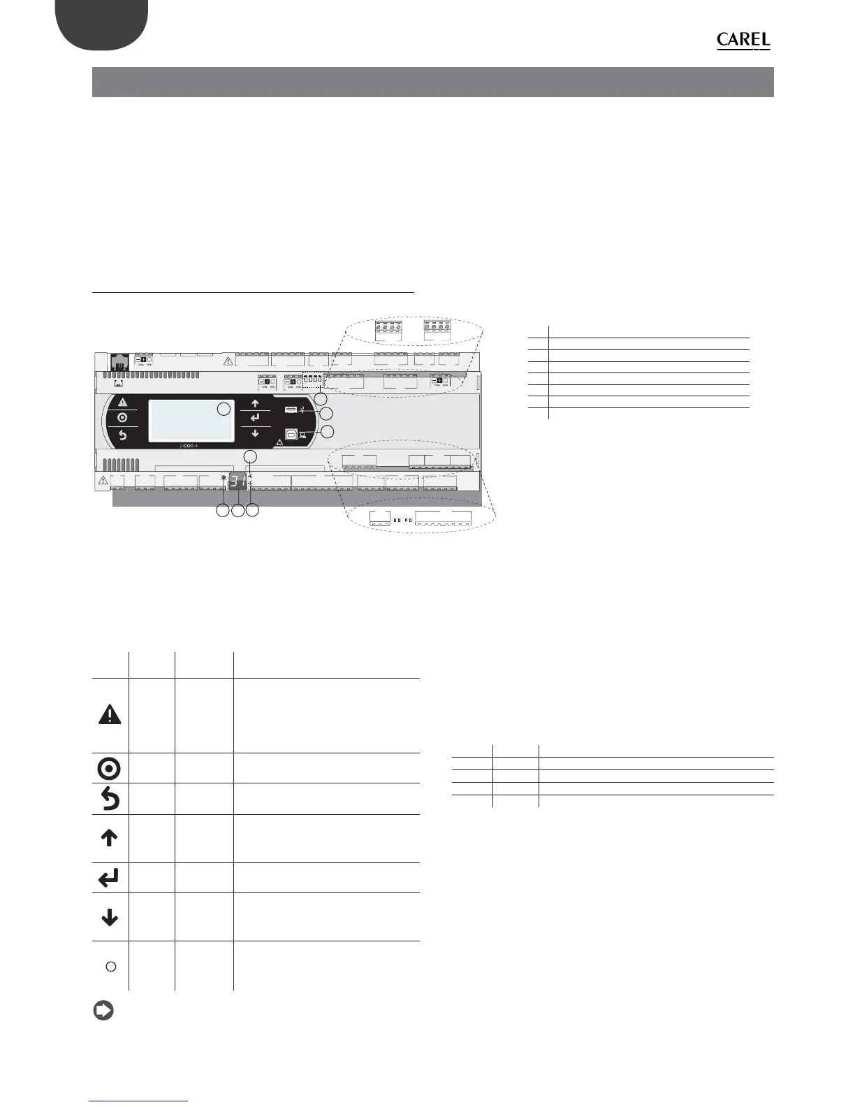
2.1 pCO5+ Design
C1
NO1
NO2
NO3
C1
C4
NO4
NO5
NO6
C4
C7
NO7
C7
NO8
C8
NC8
NO12
C12
NC12
NO13
C13
NC13
C9
NO9
NO10
NO11
C9
G
G0
U1
U2
U3
GND
+VDC
+V
term
GND
+5 VREF
U4
GND
U5
GND
VG
VG0
Y1
Y2
Y3
Y4
ID1
ID2
ID3
ID4
ID5
ID6
ID7
ID8
IDC1
U6
U7
U8
GND
ID9
ID10
ID11
ID12
IDC9
ID13H
ID13
IDC13
ID14
ID14H
J1
J24 J2 J3
J4
J5
J7
J8
J20
J21
J14
J10
J13
J12
J22
J16
J17
J18
J15
J6
J19
NO14
C14
NC14
NO15
C15
NC15
C16
NO16
NO17
NO18
C16
ID15H
ID15
IDC15
ID16
ID16H
Y5
Y6
ID17
ID18
IDC17
U9
GND
U10
GND
FieldBus card BMS card
J23 Fus2
J11 pLAN
J25
BMS2
J26
FBus2
43 2 1
A
B
CD
VBAT
G0
G
J30
GND
VREF
S1
S2
S3
S4
DI1
DI2
J29
only model with built-in driver
only model with built-in driver
J27
1
3
2
4
J28
1
3
2
4
A
B
D
H
C
G
F
E
Fig. 2.a
Each controller is provided with connectors for the inputs/outputs (see
chap. 5) and the secondary display, which has a button and a LED for
setting the pLAN address. Depending on the model, it can be supplied
with a built-in terminal and USB ports.
Keypad
Button Descr. Backlighting Functions
Alarm White/Red
• press together with UP while providing
power to change the controller’s address
(see par. 6.3).
• press together with Enter to access the
screens managed by the BIOS (see par.
6.6).
Prg White/Yellow -
Esc White go up one level
UP White
• press together with DOWN and ENTER to
change the terminal’s address (only for
PGDE terminal - see par. 6.4).
• press to increase value.
Enter White press to confi rm value.
DOWN White
• press together with UP and ENTER to
change the terminal’s address (only for
PGDE terminal - see par. 6.4).
• press to reduce value.
pLAN
address
selection
-
• pressed briefl y: displays the pLAN
address.
• long press (>5 s): procedure for changing
pLAN address (see par. 6.3).
Note: Once the application program is installed, all button
functions depend on the program and do not necessarily correspond to
the descriptions above.
Display
The controller is provided with two displays:
• the main display on the built-in terminal (if included);
• the secondary display showing the controller’s pLAN address.
LED
The more complete models are provided with 6 LEDs:
• 1 yellow LED indicating that the device is powered;
• 1 red LED indicating an overload on the +VDC (J2-5) terminal;
• 4 LEDs indicating valve status (only on pCO5+ built-in driver models).
Flashing LEDs mean the valve is moving; steadily-on LEDs mean the
valve is completely open or closed.
LED Colour Description
A Yellow close valve A (connector J27)
B Green open valve A (connector J27)
C Yellow close valve B (connector J28)
D Green open valve B (connector J28)
Microswitches
Four microswitches are provided to confi gure port J26 as a Fieldbus or
BMS port (see “Port J26 confi guration”).
USB ports
On the models where they are included, there are 2 USB ports which can
be accessed after removing the cover:
• a “host” USB port for connecting pendrives;
• a “slave” USB port for direct connection to the USB port of a computer
on which pCO Manager is installed, which can be used to upload the
application program, commissioning the system, etc.
Key:
A pLAN address selection button
B pLAN address display(*)
C Power LED
D Overload LED
E J26 port Fieldbus/BMS microswitches(*)
F Host USB port (master)(*)
G Slave USB port (device)(*)
H Main display
(*) available on P+5... models; not available on P+3...
models; see par. 8.3.