20
ENG
pCO5plus +0300020EN rel. 1.2 - 07.11.2013
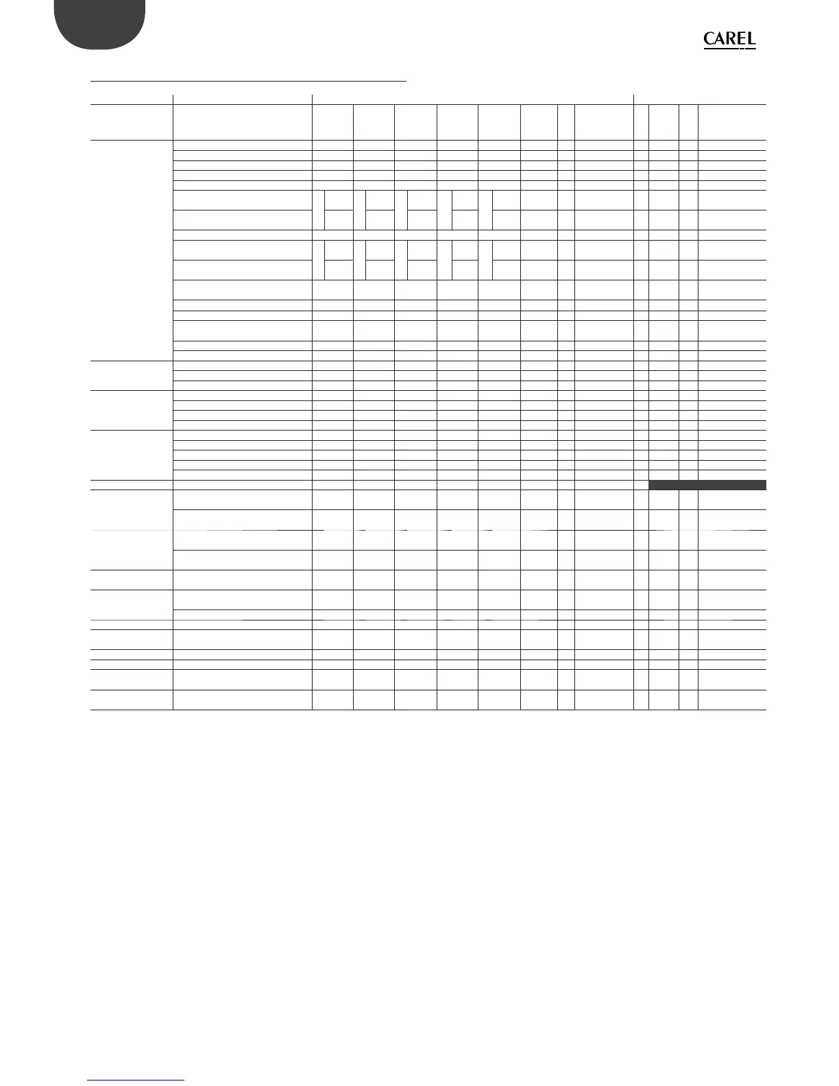
4.7 I/O table
pCO5+ Controllers pCOE I/O expansion card
Small
Medium
Large
Extra
Large
Built-in
driver
Label
In/Out
Tipo
PCOE*
Label
In/Out
Type
Universal inputs/
outputs
NTC input 5 8 10 8 8 U In Universal I/O 4 B In Analogue input(*)
PTC input 5 8 10 8 8 U In Universal I/O - - - -
PT500 input 5 8 10 8 8 U In Universal I/O - - - -
PT1000 input 5 8 10 8 8 U In Universal I/O - - - -
PT100 input max 2 max 3 max 4 max 3 max 3 U In Universal I/O - - - -
0 to 1 Vdc/0 to 10 Vdc input (**)
(powered by controller)
Tot. max 5
5
Tot. max 8
max 6
Tot. max 10
max 6
Tot. max
8
max 6
Tot. max
8
max 6 U In Universal I/O 4 B In Analogue input(*)
0 to 1 Vdc/0 to 10 Vdc input (**)
(external power supply)
5 8 10 8 8 U In Universal I/O 4 B In Analogue input(*)
0 to 5 Vdc input - - - - - - - - 4 B In Analogue input(*)
0 to 20 mA/4 to 20 mA input
(powered by controller)
Tot. max
4
max 4
Tot. max
7
max 6
Tot. max
9
max 6
Tot. max
7
max 6
Tot. max
7
max 6 U In Universal I/O 4 B In Analogue input(*)
0 to 20 mA/4 to 20 mA input
(external power supply)
max 4 max 7 max 9 max 7 max 7 U In Universal I/O - - - -
0 to 5 V input for ratiometric probe
(+5Vref)
max 5 max 6 max 6 max 6 max 6 U In Universal I/O 4 B In Analogue input(*)
Voltage-free contact digital input 5 8 10 8 8 U In Universal I/O -- -Digital input
Fast digital inputs max 2 max 4 max 6 max 4 max 4 U In Universal I/O -- -Digital input
Non-optically-isolated 0 to 10 Vdc
output
5 8 10 8 8 U Out Universal I/O -- -Analogue output
Non-optically-isolated PWM output 5 8 10 8 8 U Out Universal I/O -- -Analogue output
max tot 5 max tot 8 max tot 10 max tot 8 max tot 8
Digital inputs
Optically-isolated 24 Vac/Vdc input 8 12 14 12 12 ID In Digital input 4 ID In Digital input
24 Vac/Vdc or 230 Vac (50/60 Hz) input - 2 4 2 2 ID In Digital input - - -
max tot 8 max tot 14 max tot 18 max tot 14 max tot 14
Analogue outputs
Optically-isolated 0 to 10 Vdc output 4 4 6 4 4 Y Out
Analogue output
1 Y Out
Optically-isolated PWM output 2 2 2 2 2 Y3, Y4 Out
Analogue output
-- -
Output for two-pole stepper motor - - - - 1/2 1-3-2-4 Out
Analogue output
-- -
max tot 4 max tot 4 max tot 6 max tot 4 max tot 6
Digital outputs
NO/NC relay output 1 3 5 3 3
NO/NC Out Digital output 4 NO/NC Out Digital output
NO relay output 7 10 13 26 10
NO Out Digital output -- -
24 V SSR output
1 2 3/4 2 2 NO/NC Out Digital output -- -
230 V SSR output 1 13 3/4 2 2 NO/NC Out Digital output -- -
max tot 8 max tot 13 max tot 18 max tot 29 max tot 13
25 39 52 55 41
Total I/O
Power to terminal
1 1 1 1 1 J10
Telephone conn.
(pLAN) J10
1 1 1 1 1 +Vterm
Add’l power to
terminal
Power to probes
1 1 1 1 1 +VDC
Power to active
probes
1 1 1 1 1 +5 VREF
Power to
ratiometric probes
Power to analogue
outputs
1 1 1 1 1 VG, VG0 1 VG,VG0
pLAN ports
1 1 1 1 1 J10 Signal and power
1 1 1 1 1 J11 Signal only
Built-in Fieldbus ports 1 1 2 2 1 J23/ J26
Accessory Fieldbus
ports
1 1 1 1 1 Fbus card
Built-in BMS ports 1 1 1 1 1 J25
Accessory BMS ports 1 1 1 1 1 BMS card
Host USB port (if
included)
11111
Slave USB port (if
included)
11111
(*) On the pCOE expansion board the inputs can be selected two by two (B1, B2 and B3, B4) via software
(**) pCOE board: only 0...1V inputs
Tab. 4.e