52
ENG
pCO5plus +0300020EN rel. 1.2 - 07.11.2013
9.2 pCO Manager: operating instructions
pCO Manager is a program that lets you manage all the confi guration,
debugging and maintenance operations on CAREL pCO Sistema
devices. pCO Manager can be installed by itself or as part of the 1Tool
programming environment.
Installing pCO Manager
Go to http://ksa.carel.com and, in the section pCO Sistema, select pCO_
manager. After you accept the general conditions of the software’s free
use licence, a window will open from which you can download the fi le
pCO_manager.zip. Install the program on your computer.
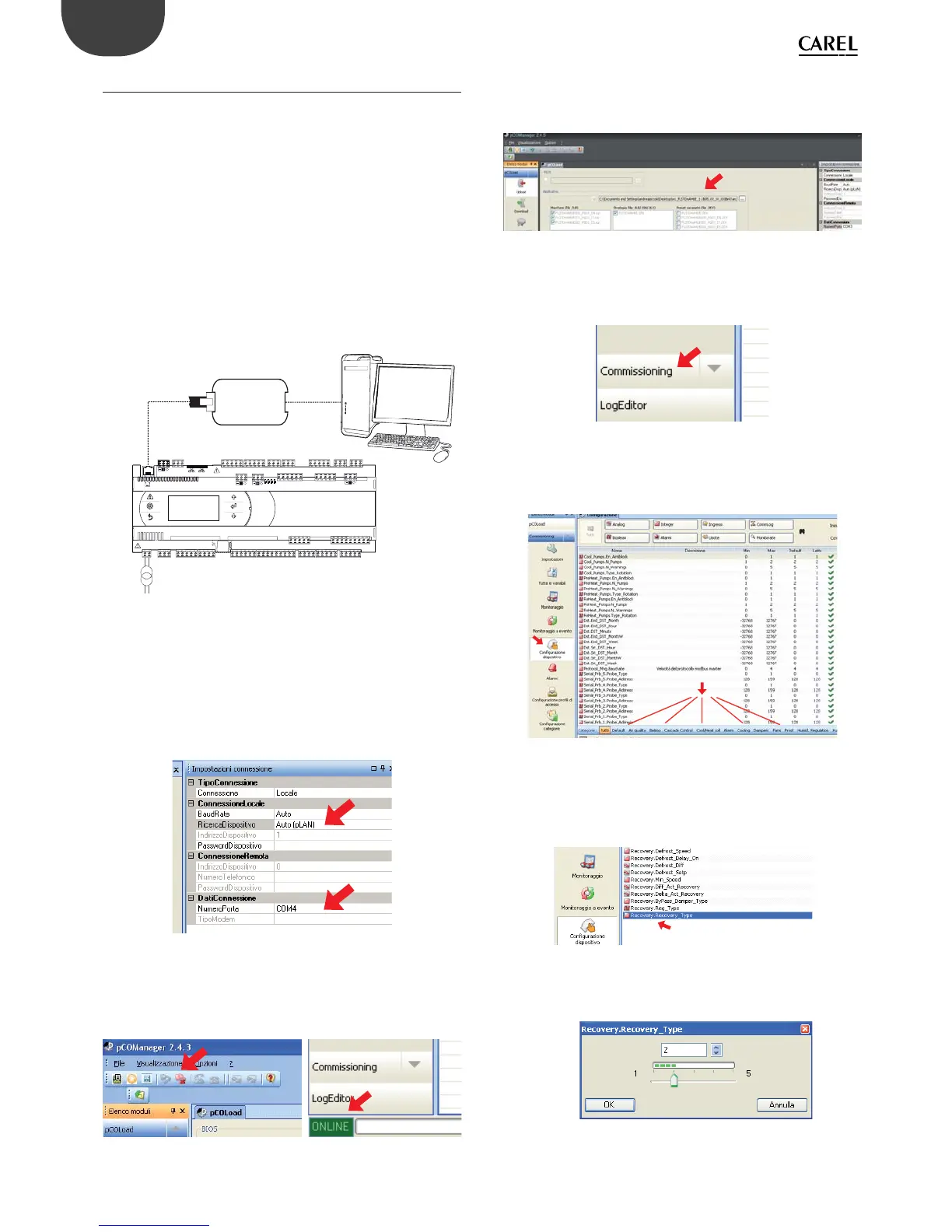
Connecting the PC to the pCO controller
Connect a cable with USB/RS485 converter to the USB port on the
computer, and connect the converter to a telephone cable plugged into
the pLAN port of the pCO. Additional connection methods are described
in par. 6.5.
J10
FieldBus card BMS card
CVSTDUTLF0
POWER SUPPLY
Fig. 9.b
Upon launching, pCO Manager will display a screen showing the
connection settings in the upper right-hand corner. Choose:
1) “connessione locale” [local connection]
2) baud rate: Auto
3) “ricerca dispositivo” [fi nd device]: Auto (pLAN)
As for the port number, follow the Wizard’s instructions for the port to be
identifi ed automatically (e.g. COM4).
Fig. 9.c
Switch the controller off and then on again and use the Connect
command to establish the connection. When the connection is
established the fl ashing message “ONLINE” will appear at the bottom left
of the screen.
Fig. 9.d
Installing the application program
Select the directory containing the application program fi les and click
“Upload” to upload the program to the pCO controller.
Fig. 9.e
Commissioning
Using the mouse, select “Commissioning” at the bottom left. A new work
environment will appear.
Fig. 9.f
Click on “confi gura dispositivo” [confi gure device] to display all the
application variables. The variables can be selected according to the
categories that appear at the bottom.
Fig. 9.g
Changing a parameter
Select the parameter category and then the parameter that you want
to edit. The parameter (e.g. recovery.recovery_type) will be highlighted
in blue.
Fig. 9.h
1) Double-click on the column marked “letto” [read]. A window will appear
in which you can enter the new value for the parameter.
Fig. 9.i