Fig. 5.t
Notes:
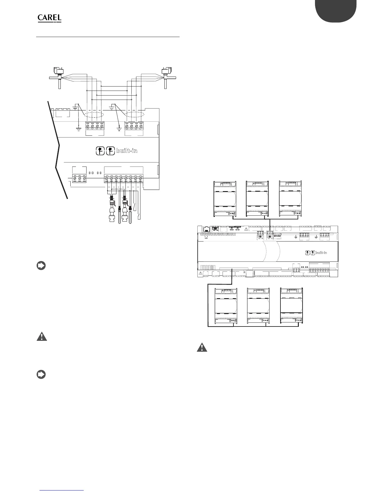
• connect the valve cable shield to the blade (faston) connector and
then earth;
• for information on the compatibility of valves and refrigerants, see the
Technical Specifi cations table and the EVD Evolution driver manual.
Apply the Ultracap module (accessory code PCOS0WUC20) on the
controller with built-in valve driver. The module is made with special
capacitors called ultracapacitors that close the electronic valve in case of
power failures. The module only powers the driver and not the controller
it is applied to.
Important: The pCO5+ with built-in driver and PCOS0WUC20
module (or EVD0000UC0 external Ultracap module and EVBAT00400
battery) must be powered at 24 Vac so that emergency valve closing is
ensured in case of power failures. If the controller is powered with DC
voltage it will not close the valve in case of power failures.
Notes:
• the built-in driver replicates all the hardware and logic functions of the
“EVD Evolution” controller in case of 1 valve and of the “EVD Evolution
TWIN” controller in case of 2 valves. In other words, it independently
controls one or two electronic expansion valves with two-pole
stepper motors. The only diff erence with EVD Evolution is that there
are no output relays. For details on the valve control logic, set-up and
installation, see the EVD Evolution manual (code +0300005IT for single
driver, +0300006IT for double driver);
• as with EVD Evolution, the internal driver on the pCO5+ controller
is available in the CAREL and the “Universal” versions. “Universal”
models are used to control both CAREL electronic expansion valves
and products made by other manufacturers (see the Technical
Specifi cations table), while CAREL models only control CAREL valves.
Serial communication and programming
Communication between the pCO5+ and its built-in driver is managed
internally through the FBus2 serial port. The FBus2 serial port (J26) is
however electrically isolated from the driver’s serial line; this ensures that
in case of external faults on the line connected to FBus2, the internal driver
can keep on working independently. The driver can only be confi gured
using the pCO5+ application developed with 1Tool; no external displays
are available for the driver.
The 1Tool development environment features a module for managing
the EVD Evolution driver. When managing the internal driver, use the
module as if you were managing an external driver connected to the
FBus2 port.
At the 1Tool application software level, the valve driver must be
connected to the FBus2 port. Consequently, any other devices physically
connected to the Fbus2 port (J26) must have the same communication
protocol (CAREL Standard Master or Modbus® Master), the same baud
rate, stop bits and parity. The CAREL or Modbus protocol is selected
automatically. The internal driver’s address is 198 (EVD Evolution’s default
address), so any other devices connected to J26 must have an address
other than 198. The CAREL or Modbus protocol is selected automatically.
External EVD Evolution drivers can be connected to the Fieldbus1 serial
port (optional card) with no address restrictions.
C1
NO1
NO2
A
B
CD
C1
C4
NO4
NO5
NO6
C4
C7
NO7
C7
NO8
C8
NC8
NO12
C12
NC12
NO13
C13
NC13
C9
NO9
NO10
NO11
C9
G
G0
U1
U2
U3
GND
+VDC
+V
term
GND
+5 V
REF
U4
GND
U5
GND
VG
VG0
Y1
Y2
Y3
Y4
ID1
ID2
ID3
ID4
ID5
ID6
ID7
ID8
IDC1
U6
U7
U8
GND
ID9
ID10
ID11
ID12
IDC9
ID13H
ID13
IDC13
ID14
ID14H
FieldBus card
BMS card
CANL
CANH
GND
J26 FBus2
OFF
43 2 1
ON
1
3
2
4
1
3
2
4
driver
VBAT
G0
G
GND
VREF
S1
S2
S3
S4
DI1
DI2
VBAT
G0
G
E
X
V connectionPower S upply Rela y
NO 1
COM 1
4231
GND
V REF
S1
S2
S3
S4
DI1
DI2
Analog – Digital Input Network
GND Tx/Rx
VBAT
G0
G
E
X
V connectionPower Supply Relay
NO 1
COM 1
4231
GND
V REF
S1
S2
S3
S4
DI1
DI2
Analog – Digital Input Network
GND Tx/Rx
VBAT
G0
G
E
X
V connectionPower Supply Rela y
NO 1
COM 1
4231
GND
V REF
S1
S2
S3
S4
DI1
DI2
Analog – Digital Input Networ k
GND Tx/Rx
VBAT
G0
G
E
X
V connectionPower Supply Relay
NO 1
COM 1
4231
GND
V REF
S1
S2
S3
S4
DI1
DI2
Analog – Digital Input Networ k
GND Tx/Rx
VBAT
G0
G
E
X
V connectionPower Supply Rela y
NO 1
COM 1
4231
GND
V REF
S1
S2
S3
S4
DI1
DI2
Analog – Digital Input Netw ork
GND Tx/Rx
VBAT
G0
G
E
X
V connectionPower Supply Rel ay
NO 1
COM 1
4231
GND
V REF
S1
S2
S3
S4
DI1
DI2
Analog – Digital Input Netw ork
GND Tx/Rx
ADDR≠198
ADDR≠198
ADDR≠198
ADDR =198
ADDR =198
Important: To ensure effi cient data exchange between the driver
and the controller, when developing the 1Tool application, if there are
devices connected to the FBus2 port (terminal J26) using the Modbus®
protocol, developers should take into account the number of variables
exchanged over the entire serial line.