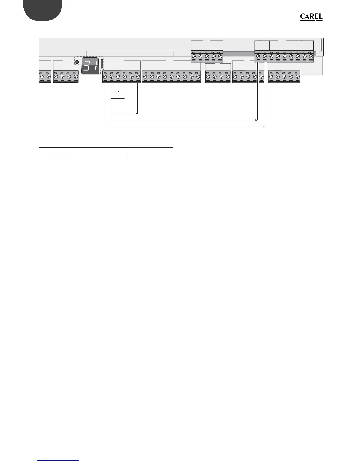
EasyManua.ls Logo

Carel pCO5+ - Page 32

Carel pCO5+
60 pages
To Next Page IconTo Next Page
To Previous Page IconTo Previous Page
Loading...
32
ENG
pCO5plus +0300020EN rel. 1.2 - 07.11.2013
Example of connection diagram (LARGE model):
GND
+VDC
U4
GND
U5
GND
VG
VG0
Y1
Y2
Y3
Y4
ID1
ID2
ID3
ID4
ID5
ID6
ID7
ID8
IDC1
U6
U7
U8
GND
ID9
ID10
ID11
ID12
I DC9
ID13H
ID13
IDC13
ID14
ID14H
J3
J4 J5 J7
J8
J20
J6
J19
ID15H
ID15
IDC15
ID16
ID16H
Y5
Y6
ID17
ID18
IDC17
U9
GND
U10
GND
e
ldBus card BMS card
2
4 Vac / 28...36 Vdc
0 V
ID1
ID2
ID3
ID4
ID5
ID6
ID7
ID8
IDC1
ID9
ID10
ID11
ID12
IDC9
ID13H
ID13
IDC13
ID14
ID14H
Vout
Vout
Vout
Vout
Vout
Vout
Fig. 5.s
Max. number di optically-isolated analogue outputs (reference VG0)
pCO5+ model Small/Medium/Extralarge Large
Outputs Y1, Y2, Y3, Y4 Y1, Y2, Y3, Y4, Y5, Y6

Table of Contents

Related product manuals