23
ENG
pCO5plus +0300020EN rel. 1.2 - 07.11.2013
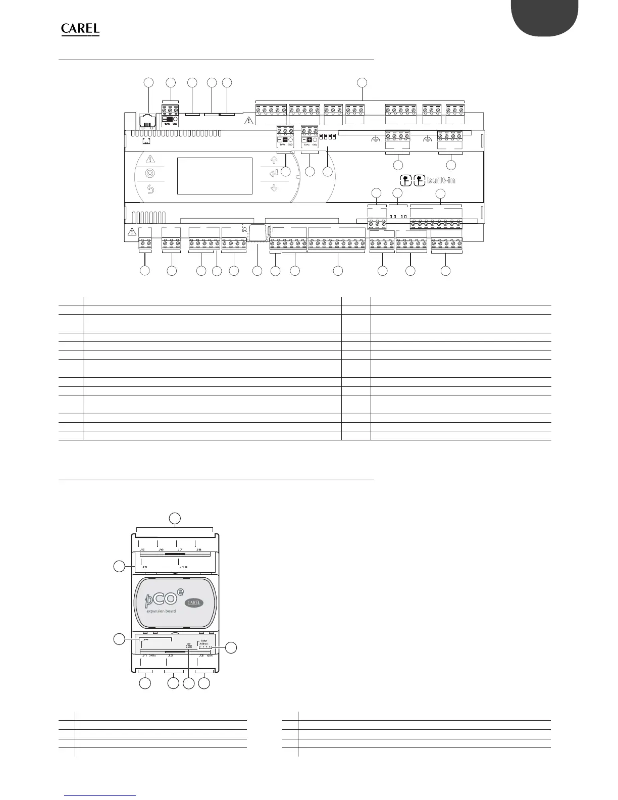
4.10 pCO5+ with built-in driver: connecting terminals
pCO5+ controllers come in two models, with one or two built-in drivers for electronic expansion valves.
C1
NO1
NO2
NO3
A
B
CD
C1
C4
NO4
NO5
NO6
C4
C7
NO7
C7
NO8
C8
NC8
NO12
C12
NC12
NO13
C13
NC13
C9
NO9
NO10
NO11
C9
G
G0
U1
U2
U3
GND
+VDC
+Vterm
GND
+5 VREF
U4
GND
U5
GND
VG
VG0
Y1
Y2
Y3
Y4
ID1
ID2
ID3
ID4
ID5
ID6
ID7
ID8
IDC1
U6
U7
U8
GND
ID9
ID10
ID11
ID12
IDC9
ID13H
ID13
IDC13
ID14
ID14H
J1
J24 J2 J3
J4
J5
J7
J8
J14
J10
J13
J12
J16
J17
J18
J15
J6
FieldBus card BMS card
J11 pLAN
J25
BMS2
J26
FBus2
43 2 1
4
5
1
6
2 3 3 3 8
9
7 8
10
11
22 24
12
15
18
16 17
20
21
13 14
J27
1
3
2
4
J28
1
3
2
4
driver
VBAT
G0
G
J30
23
GND
VREF
S1
S2
S3
S4
DI1
DI2
J29
Fig. 4.u
Ref. Description Ref. Description
1 POWER CONNECTOR G+, G0 13 Reserved
2
+Vterm: power to additional terminal
+5 VREF power to ratiometric probes
14 Reserved
3 Universal inputs/outputs 15 Relay digital outputs
4 +VDC: power to active probes 16 BMS2 connector
5 Button for setting pLAN address, secondary display, LEDs 17 Fieldbus2 connector
6
VG: voltage A(*) to optically-isolated analogue output
VG0: power to optically-isolated analogue output, 0 Vac/Vdc
18 Fieldbus/BMS selector microswitch
7 Analogue outputs 20 Electronic valve A connector
8 ID: digital inputs at voltage A(*) 21 Electronic valve B connector
9
ID..: digital inputs at voltage A(*)
IDH..: digital inputs at voltage B(**)
22
External Ultracap module (accessory) connector
10 pLAN telephone connector for terminal/downloading application program 23 Valve driver analogue and digital inputs
11 pLAN plug-in connector 24 Valve status LEDs
12 Reserved
(*) Voltage A: 24 Vac or 28 to 36 Vdc; (**) Voltage B: 230 Vac - 50/60 Hz.
4.11 pCOE: connecting terminals
The pCOE board increases the number of inputs and outputs of a pCO5+ controller when required
by the application, without having to install a larger controller.
G
ID1
ID2
ID4
ID3
IDC1
G0
VG
GND
T+
T-
VG0
Y1
B1
B3
B4
GND
NO1
C1
NC1
NO2
C2
NC2
NO3
C3
NC3
NO4
C4
NC4
+Vdc
B2
GND
+5VRef
+5VRef
+Vdc
8
7
4
1
2
5
3
6
Fig. 4.v
Ref. Description Ref. Description
1
POWER CONNECTOR G+, G0
5 Yellow power LED and 3 indicator LEDs
2
Optically-isolated analogue output, 0 to 10 V
6 Serial address
3
RS485 network connector (GND, T+, T-) or tLAN (GND, T+)
7 Analogue inputs and power to probes
4
Optically-isolated digital inputs, at 24 Vac/Vdc
8 Relay digital outputs