29
ENG
pCO5plus +0300020EN rel. 1.2 - 07.11.2013
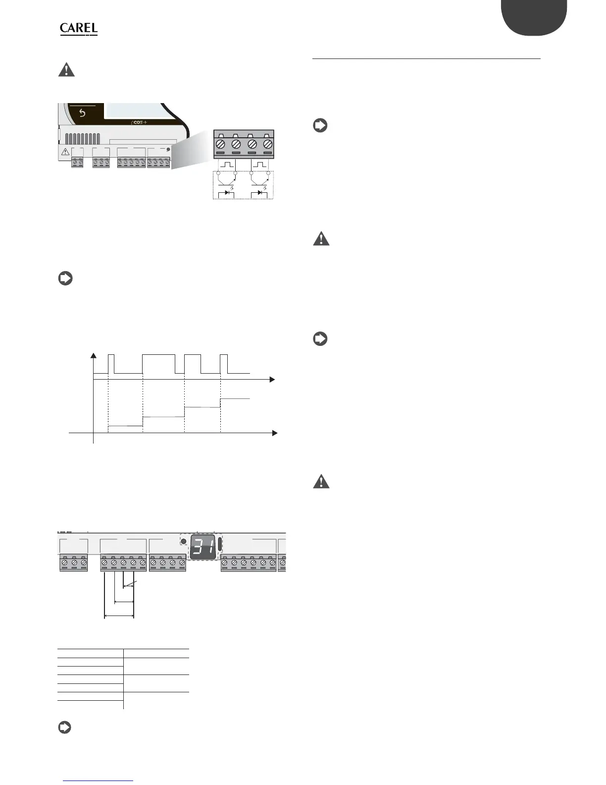
Connecting fast digital inputs
Important: The wires connecting the fast digital inputs/counters
must be shielded to avoid causing electromagnetic interference with the
probe cables.
G
G0
U1
u2
U3
GND
+VDC
+Vterm
GND
+5 VREF
U4
GND
U5
GND
J1
J24 J2 J3
FieldBus card
U4
GND
U5
GND
J3
External
impulse
generator
Fig. 5.j
The fast digital input can be used as a frequency meter. The count is
performed on the rising edge of the pulse. The pulse generator device
will have two digital outputs with transistor optocoupler, which will be
connected to the inputs as shown in the fi gure. For details on the input
signal see the Technical Specifi cations table.
Note: The BIOS shows the frequency values using specifi c variables.
If the inputs are confi gured as counters, the application program resets
the counter. The maximum number of pulses is 32767, after which the
counter restarts from zero.
Example:
t
t
input
count
Fig. 5.k
Connecting non-optically-isolated analogue outputs
There is no particular restriction on the number of outputs that can
be connected. For details on the output signal see the Technical
Specifi cations table.
Example: Analogue/PWM outputs connection diagram.
U1
U2
U3
GND
+VDC
+Vterm
GND
+5 V
REF
U4
GND
U5
GND
VG
VG0
Y1
Y2
Y3
Y4
ID1
J24 J2 J3
J4
ID1
Vout
Vout
Vout
Fig. 5.l
Key
Controller terminals Description
U1
Analogue output 1
GND
U2
Analogue output 2
GND
U3
Analogue output 3
GND
Note: The analogue outputs cannot be connected in parallel.
5.3 Digital inputs
The controller features digital inputs for connecting safety devices,
alarms, device status indicators and remote switches. These inputs are all
optically isolated from the other terminals. They can work at 24 Vac (+10/-
15%) or at 28 to 36 Vdc (-20/+10%) (indicated with ID*), and some also at
230 Vac (indicated with IDH*).
Note:
• if the control voltage is drawn in parallel with a coil, install a dedicated
RC fi lter in parallel with the coil (typical ratings are 100 Ω, 0.5 μF, 630 V);
• if the digital inputs are connected to safety systems (alarms), the
presence of voltage across the contact should be taken as the normal
operating condition, while no voltage represents an alarm situation.
This will ensure that any interruption (or disconnection) of the input
will also be signalled;
• do not connect the neutral in place of an open digital input;
• always interrupt the phase.
Important:
• to avoid electromagnetic interference, keep the probe and digital
input cables separated from the power cables as much as possible (at
least 3 cm). Never run power cables and probe signal cables in the
same conduits (including the ones in the electrical panels).
24 Vac digital inputs
The ID... digital inputs can be controlled at 24 Vac.
Note:
• the digital inputs are only functionally isolated from the rest of the
controller;
• if you want to keep the digital inputs optically isolated you will have to
provide a separate power supply for each input;
• the digital inputs can be powered at a diff erent voltage from the rest
of the controller.
Cable section
The cables used for remote connections to the digital inputs should have
the following cross-section:
Cross section for lengths <50 m = 0.25 (mm
2
)
Important: If the controller is installed in an industrial environment
(standard EN 61000-6-2) the connections must be less than 30 m long. Do
not exceed this length to avoid measurement errors.