28
ENG
pCO5plus +0300020EN rel. 1.2 - 07.11.2013
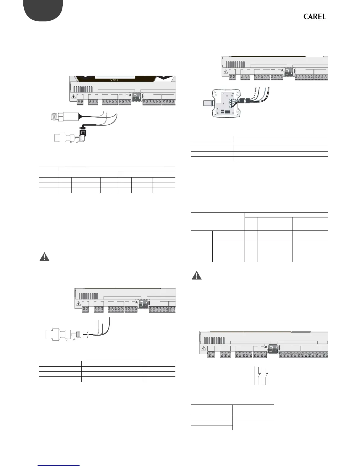
Connecting current-output pressure probes
For information on the maximum number of probes that can be
connected see the table at the beginning of this paragraph. For details
on the operating range see the data sheets supplied with the probes.
The controller can be connected to all CAREL SPK* series active pressure
probes or any commercially available pressure probes with 0 to 20 mA or
4 to 20 mA signals.
G
G0
U1
U2
U3
GND
+VDC
+Vterm
GND
+5 VREF
U4
GND
U5
GND
VG
VG0
Y1
Y2
Y3
Y4
ID1
ID2
ID3
ID4
J1
J24 J2 J3
J4
J
FieldBus card BMS card
U1
U2
U3
GND
+VDC
U4
GND
U5
GND
1
1
2
21
2
Fig. 5.f
Key
Controller
terminals
Current-output pressure probe
12
+VDC
Wire 1
Power Brown
Wire 1
Power Brown
U1
Wire 2
Signal White -
U2
Wire 2
Signal White
Connecting 0 to 5 V ratiometric pressure probes
For information on the maximum number of probes that can be
connected see the table at the beginning of this paragraph. For details
on the operating range see the data sheets supplied with the probes.
The controller can be connected to all CAREL SPKT series active pressure
probes or any commercially available pressure probes with 0 to 5 V
ratiometric signals.
Important:
• the ratiometric probes are powered by the controller through terminal
+5 VREF;
• the ratiometric probes cannot be powered by an external source.
G
G0
U1
U2
U3
GND
+VDC
+Vterm
GND
+5 VREF
U4
GND
U5
GND
VG
VG0
Y1
Y2
Y3
Y4
ID1
ID2
J1 J24 J2 J3
J4
FieldBus card BMS card
U1
U2
U3
GND
GND
+5 VREF
+VDC
Fig. 5.g
Key
Controller terminals Description Wire colour
+5 V
REF Power Black
GND Power reference Green
U1 Signal White
Connecting active probes with 0 to 10 V output
For information on the maximum number of probes that can be
connected see the table at the beginning of this paragraph. For details
on the operating range see the data sheets supplied with the probes.
G
G0
U1
U2
U3
GND
+VDC
+Vterm
GND
+5 VREF
U4
GND
U5
GND
VG
VG0
Y1
Y2
Y3
Y4
ID1
ID2
ID3
ID4
J1
J24 J2 J3
J4
J
FieldBus card BMS card
U1
U2
U3
GND
+VDC
M
out T
+ (G)
out H
Fig. 5.h
Key
Controller terminals 0 to 10 V active probes
GND Reference
+VDC Power
U1 Signal 1
U2 Signal 2
Max. number of connectable digital inputs
The controller allows the universal inputs/outputs to be confi gured as
non-optically isolated, voltage-free digital inputs. In any case, the inputs
must be connected to a voltage-free contact.
Max. number of digital inputs connectable
to universal inputs/outputs
Type of signal
pCO5+
Small
Medium/ Built-in
driver/ Extralarge
Large
Digital
inputs (not
optically
isolated)
- voltage-free
contacts
58 10
- fast digital
inputs
max 2
4
(max 2 su U1...U5,
max 2 su U6..U8)
6
(max 2 su U1...U5,
max 2 su U6...U8,
2 su U9...U10)
Tab. 5.c
Important: The maximum current allowed on the digital input is
10 mA. Therefore the rating of the external contact must be at least
10 mA.
Connecting the ON/OFF inputs
There is no particular restriction on the maximum number of inputs that
can be connected. For details on the operating range see the Technical
Specifi cations table.
G
G0
U1
U2
U3
GND
+VDC
+Vterm
GND
+5 VREF
U4
GND
U5
GND
VG
VG0
Y1
Y2
Y3
Y4
ID1
ID2
ID3
ID4
ID5
ID6
ID7