27
ENG
pCO5plus +0300020EN rel. 1.2 - 07.11.2013
Connecting NTC, PTC temperature probes
For information on the maximum number of probes that can be
connected see the table at the beginning of this paragraph. For details
on the operating range see the Technical Specifi cations table.
G
G0
U1
U2
U3
GND
+VDC
+Vterm
GND
+5 VREF
U4
GND
U5
GND
VG
VG0
Y1
Y2
Y3
Y4
ID1
ID2
ID3
ID4
ID5
ID6
ID7
J1
J24 J2 J3
J4 J5
FieldBus card BMS card
U1
U2
U3
GND
+VDC
U4
GND
U5
GND
1
2
3
4
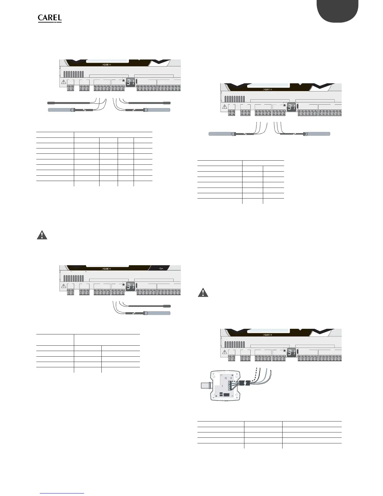
Fig. 5.b
Key
Controller terminals
NTC probe
1234
GND Wire 1
U1 Wire 2
GND Wire 1
U2 Wire 2
GND Wire 1
U4 Wire 2
GND Wire 1
U5 Wire 2
Connecting PT500/PT1000 temperature probes
For information on the maximum number of probes that can be
connected see the table at the beginning of this paragraph. For
details on the operating range see the Technical Specifi cations table.
Important:
• to ensure correct measurements from the probe each wire must be
connected to only one terminal.
• the two probe wires have no polarity.
G
G0
U1
U2
U3
GND
+VDC
+Vterm
GND
+5 VREF
U4
GND
U5
GND
VG
VG0
Y1
Y2
Y3
Y4
ID1
ID2
ID3
ID4
ID5
ID6
ID7
J1
J24 J2 J3
J4 J5
FieldBus card BMS card
input: 24 V 50...60 Hz / 28...36 V
max. power: 45 VA/20 W
U1
U2
U3
GND
+VDC
U4
GND
U5
GND
1
2
Fig. 5.c
Key
Controller
terminals
PT500/PT1000 probe
12
GND Wire 1
U4 Wire 2
GND Wire 1
U5 Wire 2
Connecting PT100 temperature probes
For information on the maximum number of probes that can be
connected see the table at the beginning of this paragraph. For details
on the operating range see the Technical Specifi cations table.
The probe has three wires: connect one to GND and the other two to two
separate but adjacent universal inputs on the same controller (e.g. U1, U2,
GND, or U4, U5, GND).
G
G0
U1
U2
U3
GND
+VDC
+Vterm
GND
+5 VREF
U4
GND
U5
GND
VG
VG0
Y1
Y2
Y3
Y4
ID1
ID2
ID3
ID4
ID5
ID6
ID7
J1
J24 J2 J3
J4 J5
FieldBus card BMS card
U1
U2
U3
GND
+VDC
U4
GND
U5
GND
1
2
Fig. 5.d
Key
Controller terminals PT100 probe
12
U1 Wire 1
U2 Wire 2
GND Wire 3
U4 Wire 1
U5 Wire 2
GND Wire 3
Connecting active temperature and humidity probes
For information on the maximum number of probes that can be
connected see the table at the beginning of this paragraph. The number
depends on the power supply used. The distinction is between probes
powered by the controller (terminal +VDC) and probes powered by an
external source, and also between active probes with voltage or current
outputs. For details on the operating range see the data sheets supplied
with the probes.
The controller can be connected to all the CAREL DP* series active temperature
and humidity probes confi gured at 0 to 1 V or 4 to 20 mA.
Important: For temperature probes use the 4 to 20 mA or NTC
confi guration, as the 0 to 1 Vdc signal is limited to the 0 to 1 V range and is
therefore not always compatible with the standard 10 mV/°C signal of CAREL
probes (at temperatures below 0 °C or above 100 °C a probe alarm may be
triggered).
G
G0
U1
U2
U3
GND
+VDC
+Vterm
GND
+5 VREF
U4
GND
U5
GND
VG
VG0
Y1
Y2
Y3
Y4
ID1
ID2
ID3
ID4
ID5
ID6
ID7
J1
J24 J2 J3
J4 J5
FieldBus card BMS card
U1
U2
U3
GND
+VDC
M
out T
+ (G)
out H
Fig. 5.e
Key
Controller terminals Probe terminals Description
GND M Reference
+VDC +(G) Probe power supply
U1 outH Humidity probe output
U2 outT Temperature probe output