37
ENG
pCO5plus +0300020EN rel. 1.2 - 07.11.2013
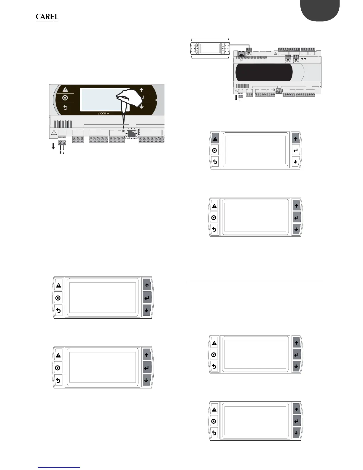
Setting the pLAN address
Procedure:
1. Press button A for 5 seconds; the pLAN address starts fl ashing.
2. Press repeatedly or hold the button until reaching the desired
address (e.g. 7), then remove the screwdriver.
3. Wait until the address starts fl ashing quickly. The address is now
saved but is not yet active for the application program.
4. Power off the controller.
5. Power on the controller. The address is now active.
G
G0
U1
u2
U3
GND
+VDC
+V
term
GND
+5 VREF
U4
GND
U5
GND
VG
VG0
Y1
Y2
Y3
Y4
Fig. 6.d
2. Setting the address using an external terminal
The controller is assigned a private (Pr=private) or shared (Sh=shared)
terminal with address 32. The external terminal can be given an address
from 0 to 32. Addresses between 1 and 32 are used by the pLAN protocol,
while address 0 identifi es the Local Terminal protocol, used for point-to-
point connections and to confi gure the controller (this can be done with
a single pGD terminal and a single pCO).
If the controller with default setting (address=1) is connected to an
external terminal (address=32), communication is established and the
external terminal replicates the display on the built-in terminal, if featured.
If however the controller has a diff erent address (e.g. 7) and the terminal
is not set to communicate with the controller at this address, once the
connection is established the terminal will display a blank screen.
In this case, proceed as follows.
Procedure:
1. Press the UP, DOWN and Enter buttons together to go to the screen
for setting the terminal address.
Display address
setting......................................:02
I/O Board address.................:07
Fig. 6.e
2. Set the display’s address to 0 to set the point-to-point connection.
Press Enter to confi rm.
Display address
setting..........:00
Fig. 6.f
3. Power off the controller.
C1
NO1
NO2
NO3
C1
C4
NO4
NO5
NO6
C4
C7
NO7
C7
NO8
C8
NC8
G
G0
U1
u2
U3
GND
+VDC
+Vterm
GND
+5 VREF
U4
GND
U5
GND
VG
VG0
Y1
Y2
Y3
Y4
ID1
ID2
ID3
ID4
ID5
ID6
ID7
ID8
IDC1
J1
J24 J2 J3
J4
J5
J14
J10
J1
3
J12
J15
FieldBus card BMS card
J11 pLAN
J25
BMS2
J26
FBus2
43 2 1
Fig. 6.g
4. Power on the controller while pressing the Alarm and Up buttons
together until the following screen appears.
#######################
selftest
please wait...
#######################
Fig. 6.h
5. Using the UP and DOWN buttons, set the controller’s pLAN address
to 7 and press Enter to confi rm.
pLAN address: 7
UP: increase
DOWN: decrease
ENTER: save & exit
Fig. 6.i
6.4 Setting the terminal’s address and
connecting the controller to the
terminal
After setting the controller’s network address (see previous paragraph), to
establish connections between the controller and the terminal you need
to set the terminal’s address.
Procedure:
1. Press the UP, DOWN and Enter buttons together. The screen for
setting the terminal’s address is displayed. Set the address to 2 and
press Enter to confi rm.
Display address
setting..........:02
Fig. 6.j
2. Press the UP, DOWN and Enter buttons together. Press Enter twice and set
the controller’s address: 7. Press Enter to confi rm.
Display address
setting...........:02
I/O Board address:07
Fig. 6.k