50
ENG
pCO5plus +0300020EN rel. 1.2 - 07.11.2013
8.2 Conformity to standards
Electrical safety EN 60730-1, EN 60730-2-9, EN 61010-1, UL60730
Electromagnetic
compatibility
Versions without valve driver: EN 61000-6-1, EN 61000-6-2, EN 61000-6-2/EC, EN 61000-6-2/IS1, EN 61000-6-3, EN 61000-6-4; EN 55014-1,
EN 55014-2, EN 55014-2/EC, EN 55014-2/A1, EN 55014-2/IS1, EN 55014-2/A2
Versions with valve driver, with or without Ultracap module: EN 61000-6-1, EN 61000-6-2, EN 61000-6-2/EC, EN 61000-6-2/IS1, EN61000-
6-3, EN 61000-6-4
Tab. 8.a
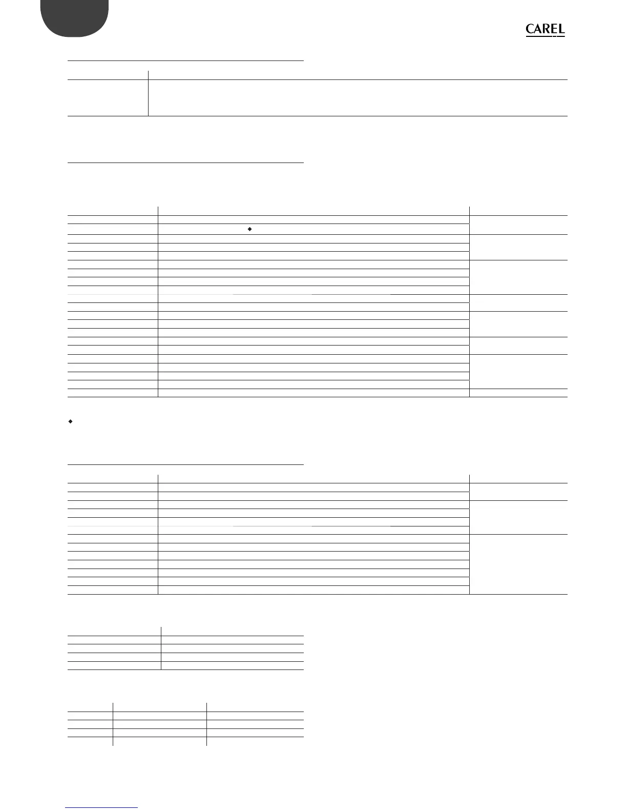
8.3 Models
The following table shows the characteristics of the models, divided by
code number. For the purchase code numbers please refer to the price
list.
Code Description Classifi cation
P+5********** 9 MB+4MB memory log fi le
Memory
P+3**********
5 MB+2MB memory log fi le (
)
P+5*****0**** Relay digital outputs
Type of digital outputP+5*****1...6**** 1 to 6 SSR outputs at 24 V
P+5*****A...F**** 1 to 6 SSR outputs at 230 V
P+5****0***** Standard
Connectivity
P+5****A***** Non-optically-isolated BMS2/Non-optically-isolated Fieldbus2
P+5****B***** Optically-isolated BMS2/Non-optically-isolated Fieldbus2
P+5****C***** Optically-isolated BMS2/Optically-isolated Fieldbus2
P+5***0****** No USB port
USB port
P+5***A****** USB port
P+5******0*** Without valve driver
Valve
driver
P+5******1*** 1 CAREL valve driver
P+5******2*** 2 CAREL valve drivers
P+5*******0** Without terminal Built-in
terminal
P+5*******E** Con PGD1 terminal
P+5********S* Small
Size
P+5********M* Medium
P+5********L* Large
P+5********Z* Extralarge
P+5*********0/1 Single/multiple Packaging
Tab. 8.b
On models P+3**B00*0(0,E)(S,M,L,Z)0
8.4 Connectors
Code Description Classifi cation
P+**CON*** CAREL standard
Type
P+**C***** Customer personalization
P+*****0** Screw-on
Type of terminal
P+*****1** With spring
P+*****2** Insulated
P+*****3** Crimp-on
P+******X0 Compact
Size
P+******S0 Small
P+******M0 Medium
P+******L0 Large
P+******Z0 Extralarge NO
P+******10 Medium 1 driver
P+******20 Medium 2 drivers
Tab. 8.c
Electrical specifi cations of plug-in connectors used
Type of connector
Pitch 5,08
Cable size 0,25 mm
2
- 2,5 mm
2
(AWG: 24 a 12)
Stripping length 7 mm
Screw thread M3
Tightening torque 0,5...0,6 Nm
Tab. 8.d
Cable AWG and size cross-reference
AWG
Size (mm
2
) MAX. current
20 0,5 2
15 1,5 6
14 2,5 8
Tab. 8.e