31
ENG
pCO5plus +0300020EN rel. 1.2 - 07.11.2013
230 Vac digital inputs
Medium and Extralarge models feature one group of 230 Vac inputs
(terminal J8), while Large models have two groups (on terminals J8 and
J19). Each group consists of two digital inputs that can be powered at 230
Vac, indicated with IDH*, and two inputs that can be powered at 24 Vac/
Vdc, indicated with ID*.
The two groups of 230 Vac inputs have double insulation between
themselves and between them and the controller. The digital inputs that
are connected can be the 24 Vac/dc inputs of one group and the 230 Vac
inputs of the other.
The two inputs of each group have the same common pole. Operational
insulation is used. In each group, the digital inputs must be powered
at the same voltage (24 Vac, 28 to 36 Vdc or 230 Vac) in order to avoid
dangerous short-circuits and/or the risk of powering lower-voltage
circuits with 230 Vac electricity.
Note:
• the range of uncertainty of the switching threshold is from 43 to 90 Vac;
• the voltage must be 230 Vac (+10/-15%), 50/60 Hz.
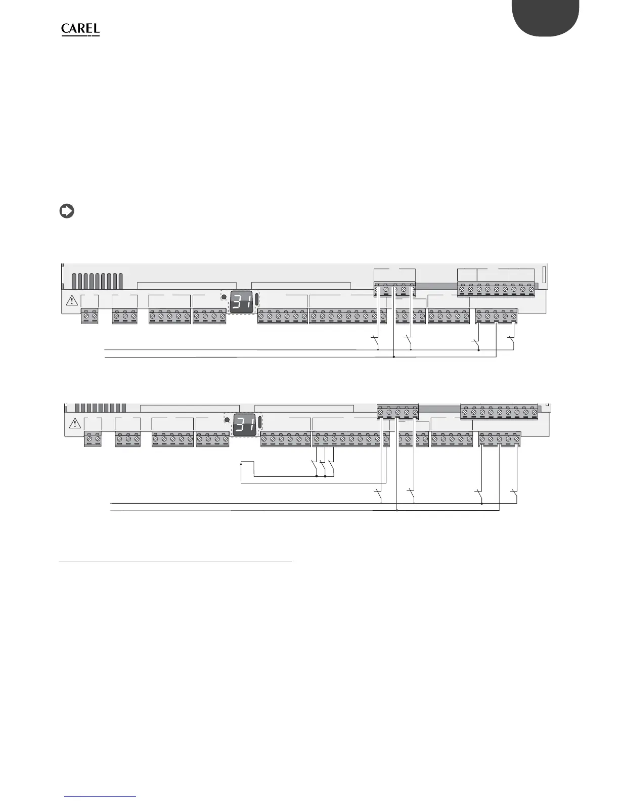
Example 1: Connection diagram with inputs at 230 Vac.
G
G0
U1
U2
U3
GND
+VDC
+Vterm
GND
+5 VREF
U4
GND
U5
GND
VG
VG0
Y1
Y2
Y3
Y4
ID1
ID2
ID3
ID4
ID5
ID6
ID7
ID8
IDC1
U6
U7
U8
GND
ID9
ID10
ID11
ID12
IDC9
ID13H
ID13
IDC13
ID14
ID14H
J1
J24 J2 J3
J4 J5 J7
J8
J20
J6
J19
ID15H
ID15
IDC15
ID16
ID16H
Y5
Y6
ID17
ID18
IDC17
U9
GND
U10
GND
FieldBus card BMS card
230 Vac
L
N
Fig. 5.q
Example 2: Connection diagram with digital inputs at diff erent voltages.
G
G0
U1
U2
U3
GND
+VDC
+Vterm
GND
+5 VREF
U4
GND
U5
GND
VG
VG0
Y1
Y2
Y3
Y4
ID1
ID2
ID3
ID4
ID5
ID6
ID7
ID8
IDC1
U6
U7
U8
GND
ID9
ID10
ID11
ID12
IDC9
ID13H
ID13
IDC13
ID14
ID14H
J1
J24 J2 J3
J4 J5 J7
J8
J6
230 Vac
L
N
-
+
24 Vdc
Fig. 5.r
5.4 Optically-isolated analogue outputs
0 to 10 V analogue outputs
On terminals VG and VG0 the controller provides optically-isolated 0 to
10 V analogue outputs, to be powered externally at the same voltage
powering the controller, i.e. 24 Vac or 28 to 36 Vdc. La fi gure below
shows the connection diagram. The 0 V supply voltage is also the voltage
reference of the outputs. See the Technical Specifi cations table for details
on the output current, output impedance, etc.
Note:
• the analogue output can be connected to module code CONVONOFF0
to convert the 0 to 10 V output into an ON/OFF relay output;
• a 0 to 10 Vdc analogue output can be connected in parallel to other
outputs of the same type, or alternatively to an external source of
voltage. The higher voltage will be considered. Correct operation is not
guaranteed if actuators with voltage inputs are connected;
• if optical isolation is not required, the VG-VG0 analogue outputs can be
powered at the same voltage on G-G0: connect G0 to VG0 and G to VG.