19
ENG
pCO5plus +0300020EN rel. 1.2 - 07.11.2013
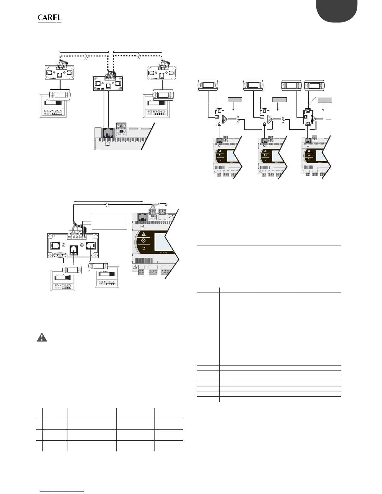
B.2 Distance 50< L< 200 m.
Use 3 TCONN6J000 boards connected as shown in the fi gure.
J10
J11 pLAN
L < 200 m
L < 200 m
6543 210
cavo telefonico
telephone cable
6543 210
6543 210
on/off alarm enter
menu I/O set prog.
?
info
Graphic
on/off alarm enter
menu I/O set prog.
?
info
Graphic
0,8 m MAX
Fig. 4.n
B.3 Distance 200< L< 500 m.
If one of the terminals is connected at a distance >200 m, connect it
according to the layout described in A.3. Connect the other terminal as
described in A.1 or A.2. If both terminals are close to a distance >200 m,
connect them as shown in the layout below.
on/off alarm enter
menu I/O set prog.
?
info
Graphic
on/off alarm enter
menu I/O set prog.
?
info
Graphic
G
G0
U1
u2
U3
GND
+Vterm
GND
+5 VREF
J1
J24 J2
J10
J11 pLAN
J31
CANL
CANH
GND
L < 500 m
J14 and J15 on 2-3
on TCONN6J000
AWG20/22
1 twisted pair
6543210
+
-
alimentatore
power supply
20...30 Vdc -150 mA
Fig. 4.o
Case C: 3 terminals
For the fi rst 2 terminals refer to Case B. For the third terminal use one of
connections A.1, A.2 or A.3.
Important:
• except for pGD1, the other terminals should be always powered by
separate power supplies;
• the 24 Vdc on the +Vterm (J24) terminal can be used only in alternative
to connector J10 to power an external terminal, with maximum current
1.5 W;
• in networks with star layout, if the cable is longer than 5 m connect
the terminal only to the fi rst or last pCO5+ in the network (to avoid
branches).
The following table applies.
Type of
cable
MAX distance
controller-terminal (m)
Power supply
Board TCON-
N6J000 used
1 Telephone 50
Provided by con-
troller (150 mA)
NO
2
AWG24
shielded
200
Provided by con-
troller (150 mA)
YES
3
AWG20/22
shielded
500 Separate YES
Tab. 4.c
2: pCO controller in pLAN network
If a terminal is connected to a pCO controller which is itself connected
to other controllers in a pLAN network, the terminal is directly powered
by the controller. Be sure to avoid the terminal being powered by two
power supplies. For that purpose, set jumpers J14 and J15 on board
TCONN6J000 to interrupt the supply current.
T
T
T
C
B
AA
A
B
B
C
C
Term 1
Term 2
Term n
sc
sc
sc
J14/ J15 ON 2-3
Term n+ 1
no 30V=
AWG24
(2 twisted pair)
AWG24
(2 twisted pair)
AWG24
(3 twisted pair)
J14/ J15 ON 2-3
J14/ J15 ON 1-2
G
G0
U1
u2
U3
GND
+Vterm
GND
+5 VREF
J1
J24 J2
J10
J11 pLAN
G
G0
U1
u2
U3
GND
+Vterm
GND
+5 VREF
J1
J24 J2
J10
J11 pLAN
G
G0
U1
u2
U3
GND
+Vterm
GND
+5 VREF
J1 J24 J2
J10
J11 pLAN
no 30V=
30V=
Fig. 4.p
When setting up a pLAN network with pCO controllers and terminals,
each pCO5+ controller can power only 1 PGD1/E terminal (except for the
Small model, which can power 2 terminals). When you need to connect
more than one terminal, you will have to provide an independent power
supply. See instructions sheet code +050002895.
4.6 Input/output labels
pCO5+ controllers are distinguished by size and provided with inputs
and outputs and power supplies for the active probes most suitable for
various applications.
The features that depend on the model are:
• maximum number and type of inputs/outputs;
• availability of built-in driver for expansion valves.
Label Type of signal
U... Universal inputs/outputs, confi gurable via software as:
Analogue inputs:
- NTC, PTC, PT500, PT1000 sensors
- PT100 sensors
- 0 to1 Vdc or 0 to 10 Vdc signals
- 0/4 to 20 mA signals
- 0 to 5 V signals for ratiometric probes
Digital inputs (not optically isolated):
- potential-free contacts (not optically isolated)
- fast digital inputs
Analogue outputs (not optically isolated):
- 0 to 10 Vdc signals
- PWM signals
Y... 0 to 10 Vdc analogue outputs, PWM outputs
ID... 24 Vac/24 Vdc digital input
ID...H 230 Vac digital input
NO... Relay output, normally open contact
NC... Relay output, normally closed contact
C... Relay output, common
Tx/Rx, GND Serial port
Tab. 4.d