13
ENG
pCO5plus +0300020EN rel. 1.2 - 07.11.2013
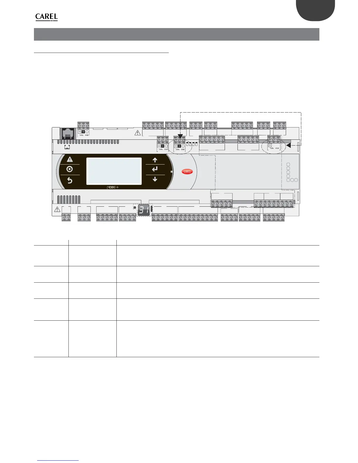
3. COMMUNICATION PORTS
3.1 Serial ports
Compared to the pCO3, pCO5+ (and pCO5) controllers have a second
BMS serial port on connector J25 (BMS2) and a second Fieldbus port
on connector J26 (FBus2). pCO5+ Large and Extralarge boards still have
connector J23, which is marked FBus2 like connector J26. With reference
to management under 1Tool, this is the same serial line, so diff erent
addresses must be used for devices connected to both connectors,
while from the electrical point of view the ports are independent (an
electrical fault on port J26 does not aff ect port J23). See the “Technical
Specifi cations” table.
C1
NO1
NO2
NO3
C1
C4
NO4
NO5
NO6
C4
C7
NO7
C7
NO8
C8
NC8
NO12
C12
NC12
NO13
C13
NC13
C9
NO9
NO10
NO11
C9
G
G0
U1
U2
U3
GND
+VDC
+Vterm
GND
+5 VREF
U4
GND
U5
GND
VG
VG0
Y1
Y2
Y3
Y4
ID1
ID2
ID3
ID4
ID5
ID6
ID7
ID8
IDC1
U6
U7
U8
GND
ID9
ID10
ID11
ID12
IDC9
ID13H
ID13
IDC13
ID14
ID14H
J1
J24 J2 J3
J4
J5 J7
J8
J20
J21
J14
J10
J13
J12
J22
J16
J17
J18
J15
J6
J19
NO14
C14
NC14
NO15
C15
NC15
C16
NO16
NO17
NO18
C16
ID15H
ID15
IDC15
ID16
ID16H
Y5
Y6
ID17
ID18
IDC17
U9
GND
U10
GND
FieldBus card BMS card
J23 FBus2
J11 pLAN
J25 BMS2
J26 FBus2
43 2 1
ONLY FOR
LARGE AND EXTRALARGE
MODELS
Fig. 3.a
Serial Type/Connector Features
Serial ZERO pLAN/J10, J11
• Built into main board
• HW driver: asynchronous half duplex RS485 pLAN
• Not optically isolated
• Connectors: telephone jack + 3-pin plug-in connector
Serial ONE BMS 1 Serial Card
• Not built into main board
• HW driver: not present
• Can be used with all the BMS expansion cards of the pCO family
Serial TWO FieldBus 1 Serial Card
• Not built into main board
• HW driver: not present
• Can be used with all Fieldbus expansion cards of the pCO family
Serial THREE BMS 2 / J25
• Built into main board
• HW driver: asynchronous half duplex RS485 slave
• Optically-isolated/non-optically-isolated serial
• 3-pin plug-in connector
Serial FOUR FieldBus 2 / J26
(and J23 on Large and
Extralarge versions)
• Built into main board
• HW driver: asynchronous half duplex RS485 Master or Slave (see par. 3.2)
• J23: not optically isolated
• J26: optically isolated/not optically isolated
• 3-pin plug-in connector
• J23 and J26 are both managed by the same protocol as serial 4, with the advantage of being electrically
independent.
Tab. 3.a