47
ENG
pCO5plus +0300020EN rel. 1.2 - 07.11.2013
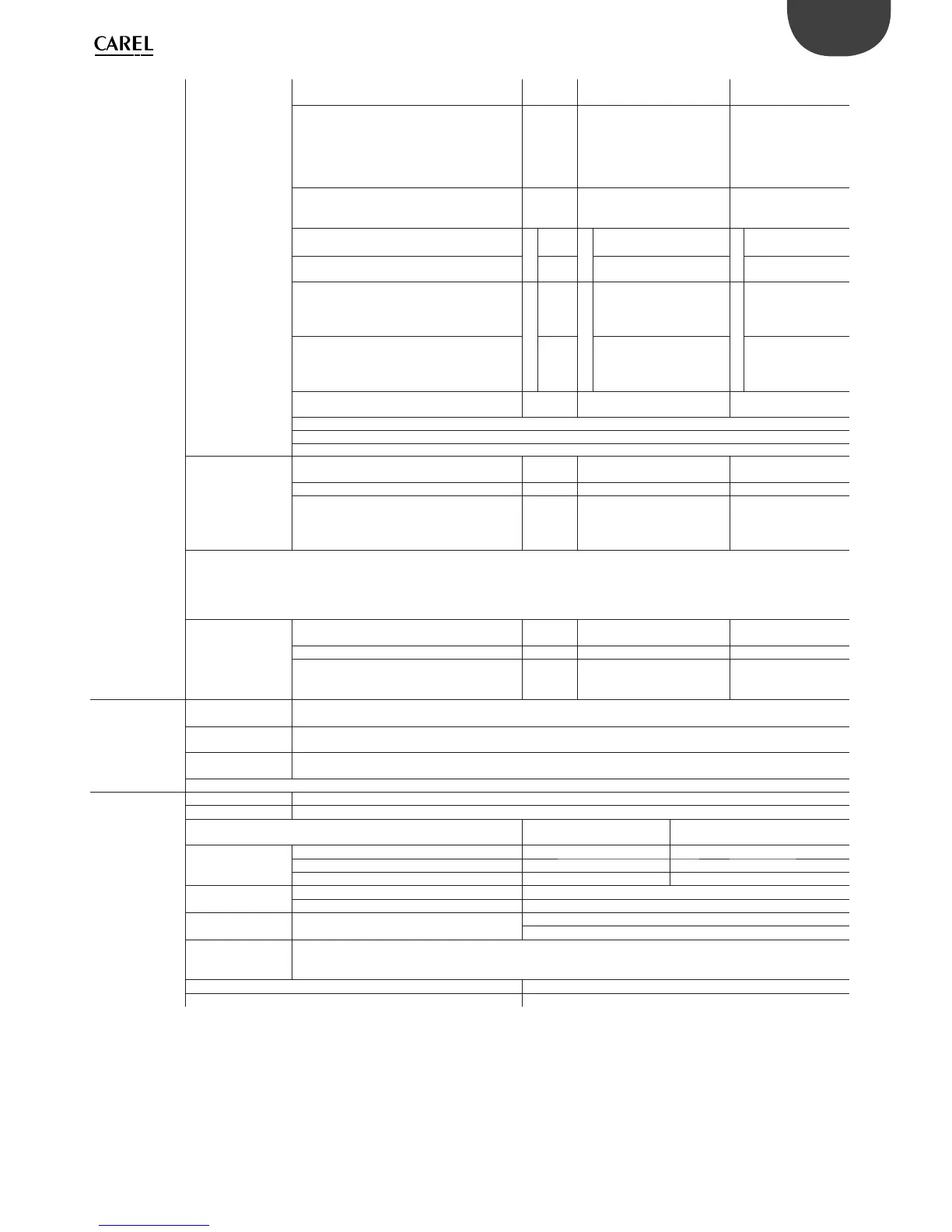
Universal inputs/
outputs
U...
Analogue inputs,
Lmax = 30 m (max.
no.)
SMALL
MEDIUM/ BUILT-IN DRIVER/
EXTRALARGE
LARGE
- CAREL NTC probes (-50T90°C; R/T 10 kΩ±1%
at 25°C)
- NTC HT (0T150°C)
- PTC (600Ω to 2200Ω)
- PT500 (
-100T300°C)
- PT1000 (-100T400°C)
58 10
- PT100 probes (-100T400°C) 2
3 (2 on U1 to U5,
1 on U6 to U8)
4 (2 on U1 to U5,
1 on U6 to U8, 1 on U9
to U10)
- 0 to 1 Vdc/0 to 10 Vdc signals from controller-
powered probes (*)
Tot. max. 5
5
Tot. max.
8
6
Tot. max. 10
6
- 0 to 1 Vdc/0 to 10 Vdc signals from externally
powered probes (*)
58 10
- 0 to 20 mA/4 to 20 mA inputs from controller-
powered probes (*)
Tot. max.
4
4
Tot. max.
7
6 :
(max. 4 on U1 to U5,
3 on U6 to U8)
Tot. max.
9
6
(max. 4 on U1 to U5,
3 on U6 to U8,
2 on U9 to U10)
- 0 to 20 mA/4 to 20 mA inputs from externally
powered probes (*)
4
7 :
(max. 4 on U1 to U5,
3 on U6 to U8)
9 :
(max. 4 on U1 to U5,
3 on U6 to U8,
2 on U9 to U10)
- 0 to 5 V signals from controller-powered
ratiometric probes (*)
56 6
Input accuracy: ±0.3% fs
Time constant for each input: 0.5 s
Classifi cation of measuring circuits (IEC EN 61010-1): Category I
Non-optically-isolated
digital inputs, Lmax =
30 m (max. no.)
SMALL
MEDIUM/ BUILT-IN DRIVER/
EXTRALARGE
LARGE
- Voltage-free contacts 5 8 10
- Fast digital inputs
Type: voltage-free contact
Max. current: 10 mA
Max. frequency 2 kHz and resolution ±1 Hz
max 2
4
(max. 2 on U1 to U5,
max. 2 on U6 to U8)
6
(max. 2 on U1 to U5,
max. 2 on U6 to U8,
2 on U9 to U10)
Attention:
• To avoid irreparably damaging the controller, externally powered active probes (0 to 1 V, 0 to 10 V, 0 to 20 mA, 4 to 20 mA) should be provided
with adequate current protection and the current should be <100 mA.
• Ratiometric probes can be powered by the controller only.
• at power on, universal inputs/outputs are short circuited to GND for about 500ms up to the end of the confi guration.
Non-optically-isolated
analogue outputs
(max. no.), Lmax =
30 m
SMALL
MEDIUM/ BUILT-IN DRIVER/
EXTRALARGE
LARGE
0 to 10 Vdc (*) (max. current 2 mA) 5 8 10
PWM (0/3.3 Vdc output, max. current 2 mA,
frequency: 2 kHz asynchronous, 100 Hz
asynchronous)
58 10
Power supply
for probes and
terminals
+Vdc
Active probes can be powered by the 24/21 Vdc ±10% (*) (P+5*/P+3*) available on terminal +VDC (J2). The max.
available current is 150 mA, protected against short-circuits.
+5Vref
To power the 0 to 5 V ratiometric probes use the 5 Vdc (*) (±5%) available on terminal +5VREF(J24). The max. available
current is 60mA.
Vterm
P+3**********: 21 Vdc ± 10% (*); P+5**********: 24 Vdc ± 10% (*)
To be used to power an external terminal in alternative to the one connected to J10, Pmax = 1.5 W
Attention: For lengths greater than 10 m use a shielded cable with earthed shield. In any case the max. allowable length is 30 m.
Digital inputs
ID...
IDH...
Type Optically-isolated
Lmax 30 m
no. opto-isolated inp.
24 Vac or 24 Vdc
no. opto-isolated inp. @ 24 Vac/Vdc or
230 Vac - 50/60 Hz
Maximum number
SMALL 8 None
MEDIUM/ BUILT-IN DRIVER/EXTRALARGE 12 2
LARGE 14 4
Min. pulse detection
time on digital inputs
Normally open (open-closed-open) 200 ms
Normally closed (closed-open-closed) 400 ms
Power supply to
inputs
External
IDH...: 230 Vac (+10/-15%) 50/60 Hz
ID...: 24 Vac (+10/-15%) 50/60 Hz o 28...36 Vdc (+10/-20%)
Classifi cation of
measuring circuits
(IEC EN 61010-1)
Category I: 24 Vac/Vdc (J5, J7, J20)
Category III: 230 Vac (J8, J19)
Current draw on 24 Vac/Vdc digital inputs 5 mA
Current draw on 230 Vac digital inputs 5 mA
Notes:
• to avoid electromagnetic interference, separate as much as possible the probe and digital input cables from the cables carrying inductive loads and the power
cables. Never run power cables and probe signal cables in the same conduits (including the ones in the electrical panels);
• the two 230 Vac or 24 Vac/Vdc inputs on terminals J8 (ID13, ID14) or J19 (ID15, ID16) have the same common pole and must therefore be powered at the same
voltage (230 Vac or 24 Vac/Vdc). The two inputs are provided with operational insulation; reinforced insulation is provided between the inputs and the rest of the
controller;
• ID1 to ID8, ID9 to ID12, ID17, ID18 are functionally isolated from the rest of the controller;
• for DC digital inputs (24 Vdc), either the + or the - can be connected to the common terminal;
• the rating of the external contact connected to the digital inputs must be at least 5 mA;.