76
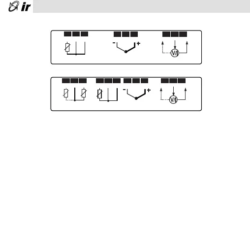
Connessione sonde / Probe connections
Pt100
TcJ/K
V/I
OUT
M
+10
1 2 37 8 9
7 8 9
7 8 9
(*)Probe Connections/ Connessione Sonde
1 2 3
Pt100
TcJ/K
V/I
OUT
M
+10
NTC
p2 p1
1 2 31 2 3
1 2 3
1 2 3
(*)Probe Connections/ Connessione Sonde
fig. 14
fig. 15
IR32
IRDR
(*) ad ogni tipo di sonda corrisponde uno specifico modello
each probe type requires its specific model
Note
1)Nel caso di sonde Pt100 a 2 fili cortocircui-
tare i morsetti 8 e 9 (IR32) o 2 e 3 (IRDR)
2)Collegare l’eventuale schermatura della
sonda alla terra del quadro elettrico. Nel
caso di termocoppie, è necessario
usare sonde con cavo schermato per
avere una corretta immunità ai disturbi
3)Per le sonde in tensione e/o corrente
considerare che la massima tensione
fornita è 10 Vdc @ 30 mA (max 8Vdc per
IRDRW).
Notes
1)The use of Pt100 2 Wires requires you to
short circuit connectors 8 and 9 (IR32) or
2 and 3 (IRDR)
2)Connect the probe braiding to the
electrical panel ground. When using
thermocouples, use screened probes
to avoid noises.
3)When using voltage or current probes
consider that the maximun voltage output
is 10 V dc @ 30mA (max 8 Vdc for
IRDRW).
+05-3015 • rel.3.0 interno ok 18-09-2002 14:31 Pagina 76

 Loading...


