Carpenter Model 860 Material Coiling Unit
Carpenter Model 860 Material Coiling Unit • Phone: (315) 682-9176 • Fax: (315) 682-9160
Website: www.carpentermfg.com • Email: wire@carpentermfg.com
Revised 05/09/2024 Page 13
Positioning Instructions for Model 93, Model 97A, Model 930, or Model 970
The Model 93, Model 97A, Model 930, or Model 970 feature different output setups than the
Model 36A/36B or Model 360.
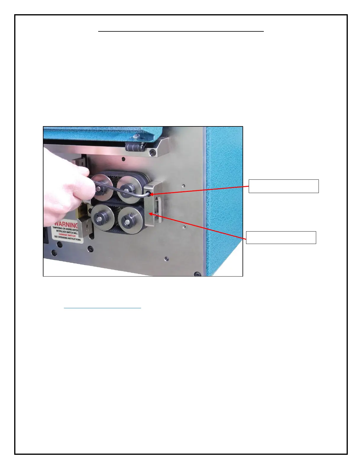
1. Before processing and coiling material, the operator must remove the PN 8813 output
guide on the Model 93, Model 97A, Model 930, or Model 970. Using a 9/64” hex
wrench, remove the PN 7214 cap screw that holds the PN 8813 output guide onto the
machine face plate.
Figure 7: Removing the Output Guide
2. Take the PN 8699 straight tube adapter out of the machine parts bag (outlined in the
Assembling the Model 860 section of the operator’s manual). This will be fastened onto
the machine face plate where the PN 8813 output guide was fastened. Align the top hole
of the PN 8699 straight tube adapter with the hole on the machine face plate.
3. Using the PN 7214 cap screw removed in step 1 above, fasten the PN 8699 straight tube
adapter to the machine face plate.
4. After installing the PN 8699 straight tube adapter to the machine face plate, position the
Model 860 so that the PN 8672 straight tube is all the way in the PN 8699 straight tube
adapter, but not protruding the other side.
5. When the PN 8672 straight tube is correctly positioned, using a 3/32” hex wrench, tighten
the PN 2922 cap screw to lock the PN 8672 straight tube into place.