Carpenter Model 860 Material Coiling Unit
Carpenter Model 860 Material Coiling Unit • Phone: (315) 682-9176 • Fax: (315) 682-9160
Website: www.carpentermfg.com • Email: wire@carpentermfg.com
Revised 05/09/2024 Page 9
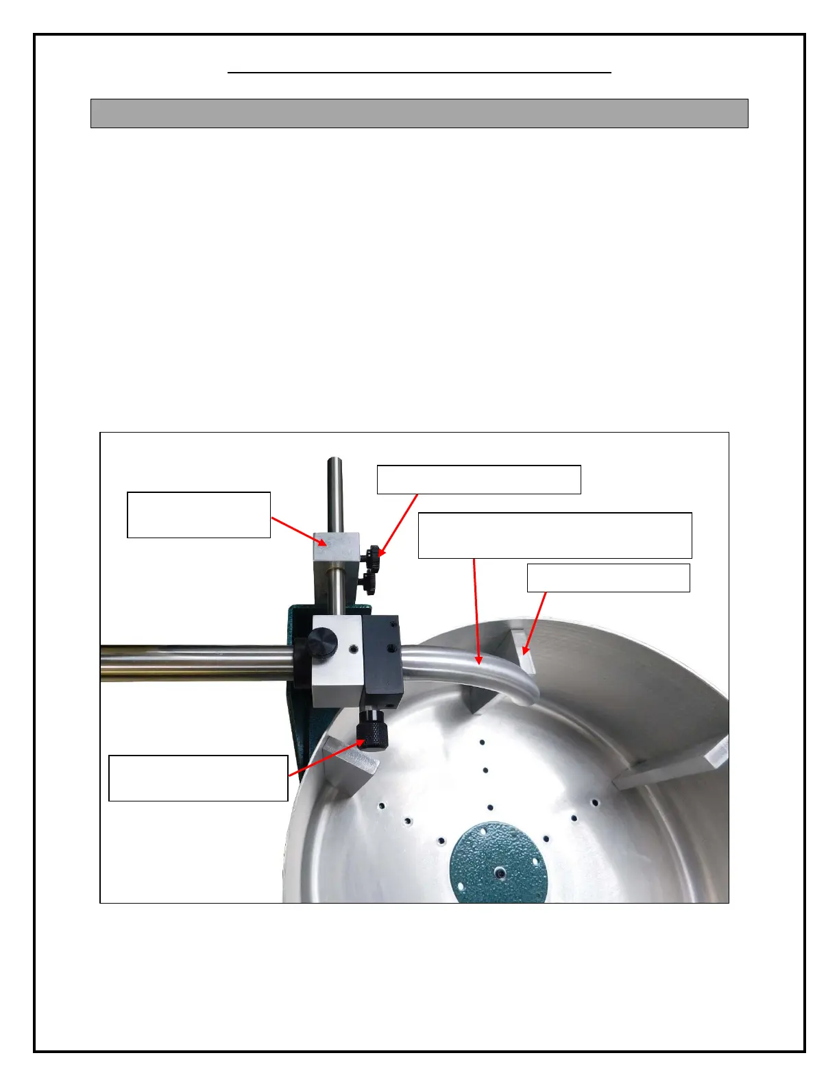
Section 2 – Positioning the Adjustable Tube Assembly
The Model 860 features coiling bowl inserts that are machined to customer specifications. For
example, if the coiling requirement is for a 10-inch finished coil diameter, the coiling bowl insert
set will be machined to accommodate this requirement. Before processing material, the
adjustable tube assembly must be correctly positioned.
1. To position the adjustable tube assembly, loosen the two (2) PN 4849 screw assemblies
on the PN 8677 slide mount assembly. Slide the adjustable tube assembly into place and
retighten the two (2) PN 4849 screw assemblies.
2. When processing material, the adjustable tube assembly must be in the down (run)
position. The opening of the PN 8666 material exit tube should be pointed down into the
coiling bowl, and the PN 8667 knob should be parallel with the coiling bowl. There
should be about 1/8”-3/16” of clearance between the PN 8666 material exit tube and the
coiling bowl inserts.
Figure 2: Positioning the Adjustable Tube Assembly (1 of 2)