22
Warning! Operating the equipment incorrectly can cause serious injury and
damage. Do not use the functions described here until you have read and com-
pletely understood all of the following documents:
- these Operating Instructions
- all "Operating Instructions" for the system components, especially the
"Safety rules"
Please see the section headed “The Set-up menu: Level 1” for information on the set-
tings, setting range and units of measurement of the available parameters.
Symbol Explanation
GPr Gas pre-flow time
I
S
Starting-current phase: The temperature is raised gently, at low welding
amperage, so that the filler metal can be positioned correctly
t
up
Upslope phase: The starting current is continuously increased, until it
reaches the welding amperage
I
1
Welding-current phase: Uniform thermal input into the base metal, whose
temperature is raised by the advancing heat
I
2
Reduced-current phase: Intermediate lowering of the welding amperage, in
order to prevent any local overheating of the base metal
t
2
Downslope phase: The welding current is continuously lowered, until it
reaches the final current.
I
E
End-crater (final-current) phase: To prevent any local overheating of the
base metal due to heat build-ups towards the end of welding. This eliminates
any risk of weld drop-through.
SPt Spot-welding time
G-H/G-L Gas post-flow time
G-H Gas post-flow time at maximum welding amperage
G-L Gas post-flow time at minimum welding amperage
Symbols and
their explanati-
ons
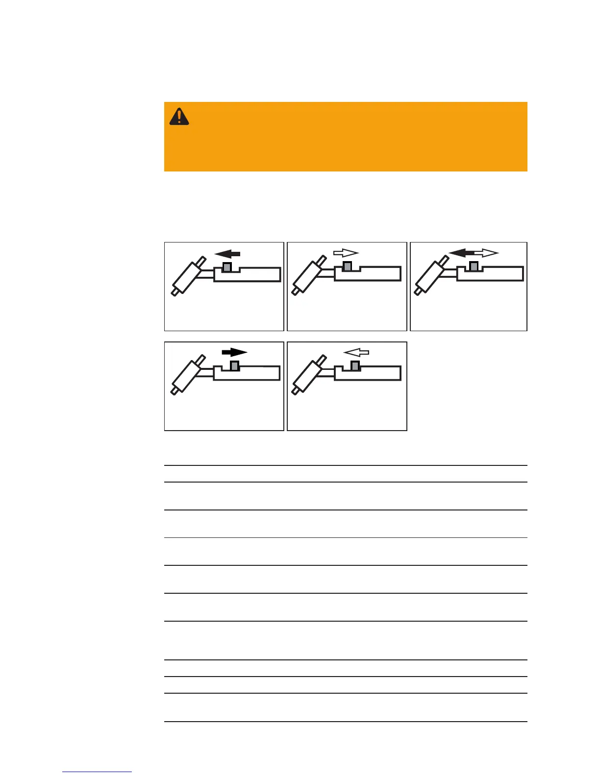
Push forward and hold the
torch trigger
Release the torch trigger Briefly push forward the
torch trigger (< 0.5 s)
Pull back and hold the
torch trigger
Release the torch trigger
TIG operating modes
General remarks