12
cdvi.com
cdvigroup.com
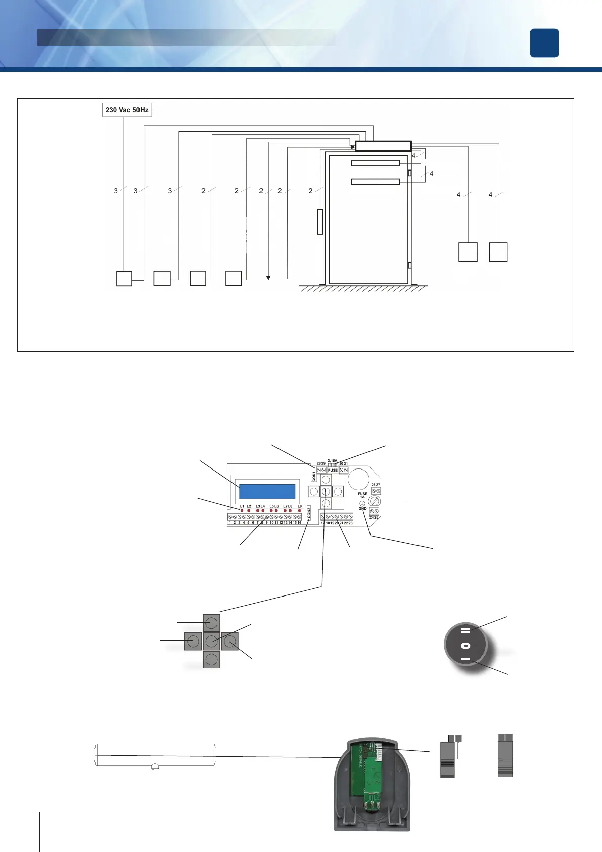
Electronic card layout and programming buttons
Display LCD
Battery
connector
Fuse
3,15A
PE
Connection
Monitor LED’s
19-way
terminal block
7-way
terminal block
Serial
connector
Fuse
1A
ESC - back to upper level
scroll UP / increases value
scroll DOWN / decreases value
OK
Not Used
External switch
I 0 II
DOOR ALWAYS
OPEN
DOOR FREE
FULLY AUTOMATIC
Jumper for external switch exclusion
It’s possible to exclude the external switch using the jumper located on the internal
card of the left cap
Switch
excluded
JUMPER OFF
Switch
enabled
JUMPER ON
DIGIWAY PLUS
INSTALLATION MANUAL
EN
Wiring diagram
RCD residual-
current circuit
breaker
3 pos. switch
autom / door free
/ always open
NIght / Day
Start/Stop
Door open
relay
Fire-alarm
Voltage
Electrolock
FTC-S [ Stop ]
FTC [ Re-open ]
Internal
Radar
External
Radar
3 x 1,5 mm
2
3 x 0.8 mm
2
2 x 0.8 mm
2
2 x 0.8 mm
2
2 x 0.8 mm
2
2 x 0.8 mm
2
2 x 0.8 mm
2
4 x 0.25 mm
2
4 x 0.25 mm
2
6 x 0.8 mm
2
6 x 0.8 mm
2
Connect the equipment to the Mains power using the appropriate cable ( 3 x 1,5mm
2
), passing it through the rear opening of
the prole and the backplate and avoiding being too tense and touching sharp edges. At the end of the installation, connect to
the ground cable provided with the electronic card ( yellow-green ) to the corrispondent faston of the cover.