14
DIGIWAY PLUS
INSTALLATION MANUAL
EN
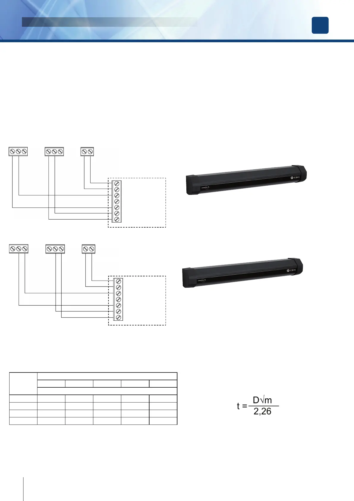
Monitored photocells wiring
The Standard EN16005 indicates that the parts of the system which have a direct effect on the safety must comply with
EN12978 and be designed to comply with EN ISO 13849-1 Performance Level “c”. Safety related parts of the control system
used for escape route functionality shall comply with EN ISO 13849-1 Performance Level “d”.
If devices type ESPE ( photocells ) are used, they must be monitored by the drive system.
Digiway Plus is equipped with output test signals ( Test1, C, Test2 ) that check the photocells status before any motion. The
system switches off for few mS the photocell through the test signal and checks the changement of the signals on the terminals
5-6 or 6-7. If the signals change regularly the door motion is enabled otherwise the motion is stopped or enabled in Low energy
( see menu Advanced options)
5 6 7 T1 C T2 20 21
Power (+)
Power (-)
Relay C
Relay NC
Test Input (-)
Test Input (+)
STOP Photocells (FTC-S)
REOPEN photocells (FTC)
LOW ENERGY mode
The Standard EN 16005 (Annex F ) indicates the parameters for the Low Energy mode : the minimum open / close time from
10° to 90° is indicated in the following table:
Width of
doorset
leaf ( m )
Mass ( Kg )
50 60 70 80 90
Time ( sec. )
0,75 3,0 3,2 3,2 3,3 3,5
0,85 3,1 3,1 3,2 3,4 3,6
1.00 3,2 3,4 3,7 4,0 4,2
1.2 3,8 4,2 4,5 4,8 5,1
for other widths and/or masses the times can be calculated
using the formula:
where t = time in sec., D = diameter doorset leaf in meters, m = mass in kg.
See on the menu ADVANCED SETTINGS how to set the doorset leaf dimensions and the operating mode in case of photocells
malfunction.
5 6 7 T1 C T2 20 21
Power (+)
Power (-)
Relay C
Relay NC
Test Input (-)
Test Input (+)