11
cdvi.com
cdvigroup.com
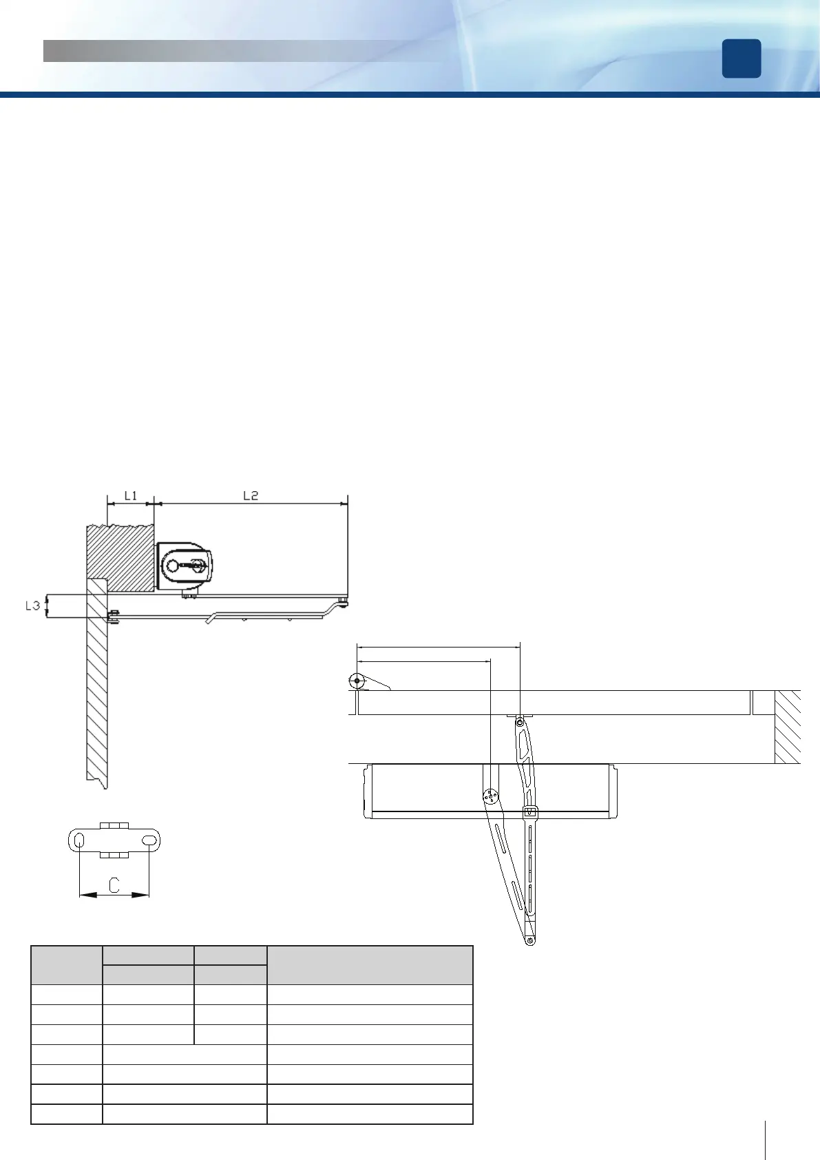
Articulated arm version
This part is addressed to outward door installations
1) Identify the dimensions of the motor, locate the xing position, the holes for the cables and the 6 xing holes making
use of the mounting template provided;
2) Make sure that the bracket of the articulated arm falls in the right position;
3) Make 6 holes diameter Ø 8 mm and insert the 6 special plugs provided ;
4) Fix the plate to the wall using the special screws provided;
5) Fix the motor to the mounting plate with the screws M6x14 provided;
6) Fix the bracket to the door referring to the distance A of the table below;
7) Plug in the articulated arm on the motor shaft and screw the xing screw M6;
8) If the distance between the motor and the door is higher than that allowed, use the extension ( optional );
9) Fix the arm to the motor by using the screw M6x14 or M6x70 provided;
10) Check full free movement whilst in free mode;
11) Make all the electrical connections;
12) Apply power;
13) Follow the procedure : «Getting started»;
14) Connect the Ground wire to the cover terminal and x the cover.
INSTALLATION MANUAL
EN
DIGIWAY PLUS
A
B
Parameter
Speed Power
Description
(mm) (mm)
A 410 430
Door hinge – door bracket distance
B 270 360
Door hinge – motor axis distance
A - B 140 70
Motor axis – door bracket distance
C 40
Bracket holes distance
L1 55 - 195
Door jamb width
L2 371
Distance wall - articulation
L3 43
Distance motor shaft-door bracket