2
How to lift up the system
Strap the system safely and securely in the slings working from
the bottom, then lift up from the ground.
This welding machine has a robust handle built into the frame for
moving the equipment.
NOTE: These hoisting and transportation devices conform to Eu-
ropean standards. Do not use other hoisting and transportation
systems.
Opening the packaging
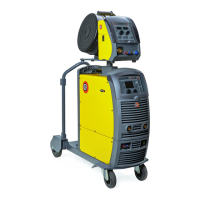
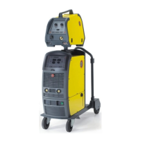
The system essentially consists of:
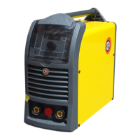
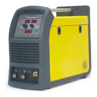
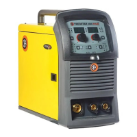
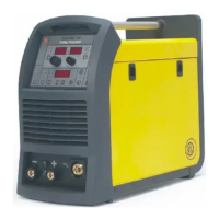
• CONVEX 330-400-500 basic weld unit.
• Separately:
- HS4 wire-feeder unit (supplied separately).
- MIG-MAG welding torch (optional).
-
Wire-feeder/generator interconnection cable (supplied sep-
arately).
- Coolant unit for welding torch (optional).
- Trolley to carry it around (optional).
Perform the following operations on receiving the apparatus:
•
Remove the welding generator and all accessories and compo-
nents from the packaging.
•
Check that the welding apparatus is in good condition; otherwise
immediately inform the retailer or distributor.
•
Check that all the ventilation grilles are open and that there is
nothing to obstruct the correct air flow.
Installation and connections
The installation site for the system must be carefully chosen in or-
der to ensure its satisfactory and safe use. The user is responsi-
ble for the installation and use of the system in accordance with
the producer’s instructions contained in this manual. Before install-
ing the system the user must take into consideration the potential
electromagnetic problems in the work area. In particular, we sug-
gest that you should avoid installing the system close to:
• Signalling, control and telephone cables.
• Radio and television transmitters and receivers.
• Computers and control and measurement instruments.
• Security and protection instruments.
Persons fitted with pace-makers, hearing aids and similar equip-
ment must consult their doctor before going near a machine in op-
eration. The equipment’s installation environment must comply to
the protection level of the frame.
The welding unit is characterised by class “S” use, which means
that the equipment can be used in settings in which there is a
heightened risk of electrical shock.
This system is cooled by means of the forced circulation of air, and
must therefore be placed in such a way that the air may be easily
sucked in and expelled through the apertures made in the frame.
Assemble the system in the following way:
• Assemble the trolley.
• Fixing the cooling unit to the trolley.
• Fixing of the welding machine to the trolley and the cooling unit
(electrical and plumbing connections).
• Fitting the feeder unit to the generator.
• Connect up the welder to the mains.
Table 1
Modell
CONVEX 330
basic
CONVEX 400
basic
CONVEX 500
basic
MIG-MAG welding
Three-phase input 50/60 Hz V 400 ± 20% 400 ± 20% 400 ± 20%
Mains supply: Z
max
Ω 0,037 0,028 0,017
Input power @ I
2
Max kVA 18,8 18,6 25,6
Delayed fuse (I
2
@ 60%) A252535
Power factor / cosφ 0,86 / 0,99 0,9 / 0,99 0,94 / 0,99
Efficiency degree η 0,82 0,88 0,89
Open circuit voltage V637070
Current range A 10-330 10÷400 10÷500
Duty cycle @ 100% (40°C) A 280 310 380
Duty cycle @ 60% (40°C) A 300 370 460
Duty cycle @ X% (40°C) A 330 (40%) 400 (50%) 500 (50%)
Wires diameter (*) mm 0,6÷1,2 (*) 0,6÷1,6 (*) 0,6÷2,0 (*)
N° rollers (*) 4 (*) 4 (*) 4 (*)
Power output of feeder motor (*) W 100 (*) 100 (*) 100 (*)
Rated wire feeding speed (*) m/min 0,5÷25 (*) 0,5÷25 (*) 0,5÷25 (*)
Spool (*)
Diameter
Weight
mm
kg
Ø300 (*)
15 (*)
Ø300 (*)
15 (*)
Ø300 (*)
15 (*)
Standards
IEC 60974-1 / IEC 60974-5 (*) / IEC 60974-10
Protection class IP 23 S IP 23 S IP 23 S
Insulation class HHH
Dimensions
mm 660 - 515 - 290 660 - 515 - 290 660 - 515 - 290
Weight kg 35 39 43
(*) On the HS4 feeder, fitted separately.
WARNING: This equipment complies with EN//IEC 61000-3-12 provided that the maximum permissible system impedance Z
max
is less than or
equal to 0,037 CONVEX 330 basic - 0,028 CONVEX 400 basic - 0,017 CONVEX 500 basic at the interface point between the user’s supply and
the public system. It is the responsibility of the installer or user of the equipment to ensure, by consultation with the distribution network opera-
tor if necessary, that the equipment is connected only to a supply with maximum permissible system impedance Z
max
less than or equal to 0,037
CONVEX 330 basic - 0,028 CONVEX 400 basic - 0,017 CONVEX 500 basic.
This system, tested according to EN/IEC 61000-3-3, meets the requirements of EN/IEC 61000-3-11.
 Loading...