12
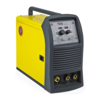
3 - SPECIAL FUNCTIONS “Fx” SELECTION
The SPECIAL FUNCTIONS “Fx” that are only available in the MIG-
MAG manual welding process are shown below. For all the other
explanations regarding this menu make reference to the relative
paragraph.
•
PRE GAS (PrG) - Provides an additional quantity of gas for a
defined time, before welding starts.
•
STARTING SPEED (StS) - Regulates the speed at which the
wire approaches the workpiece. The value indicated is a percent-
age variation in relation to the factory setting value.
• HOT START (HoT) - Regulates the current intensity for igniting
the welding arc. The value indicated is a percentage variation
in relation to the factory setting value.
•
CRATER START SPEED (F08) - Sets the initial speed of the
welding wire for the crater.
•
CRATER START VOLTAGE (F09) - Sets the initial welding volt-
age for the crater.
•
CRATER START TIME (F10) - This function defines the time
in which the current remains at the value of CRATER START
SPEED or CRATER START VOLTAGE.
•
CRATER START SLOPE (F11) - Time taken to go from the CRA-
TER START SPEED or CRATER START VOLTAGE level to the
welding speed or voltage level.
•
CRATERENDSLOPE(F12)- Time required to go from the
welding speed or voltage level to the CRATER END SPEED or
CRATER END VOLTAGE level.
• CRATER END SPEED (F13) - Sets the final speed of the weld-
ing wire for the crater.
•
CRATER END VOLTAGE (F14) - Sets the final welding volt-
age for the crater
•
CRATER END TIME (F15) - This function defines the time in
which the current remains at the value of CRATER END SPEED
or CRATER END VOLTAGE.
• SPOT WELD TIME (F07) - The time during which spot welding
takes place after the arc is ignited, after which the arc is extin-
guished automatically.
•
STITCH WELD TIME (F05) - Time in which the welding in tracts
is performed after the ignition of the arch, after which the arch
switches off automatically.
•
STITCH WELD PAUSE (F06) - Time of pause between one
welding in tracts and another.
•
BURN BACK (bUb) - Regulates the length of the wire after weld-
ing. The value indicated is a percentage variation in relation to
the factory setting value. Higher numbers correspond to more
burning of the wire.
• POST GAS (PoG) - Provides an additional quantity of gas for a
defined time, after welding ends.
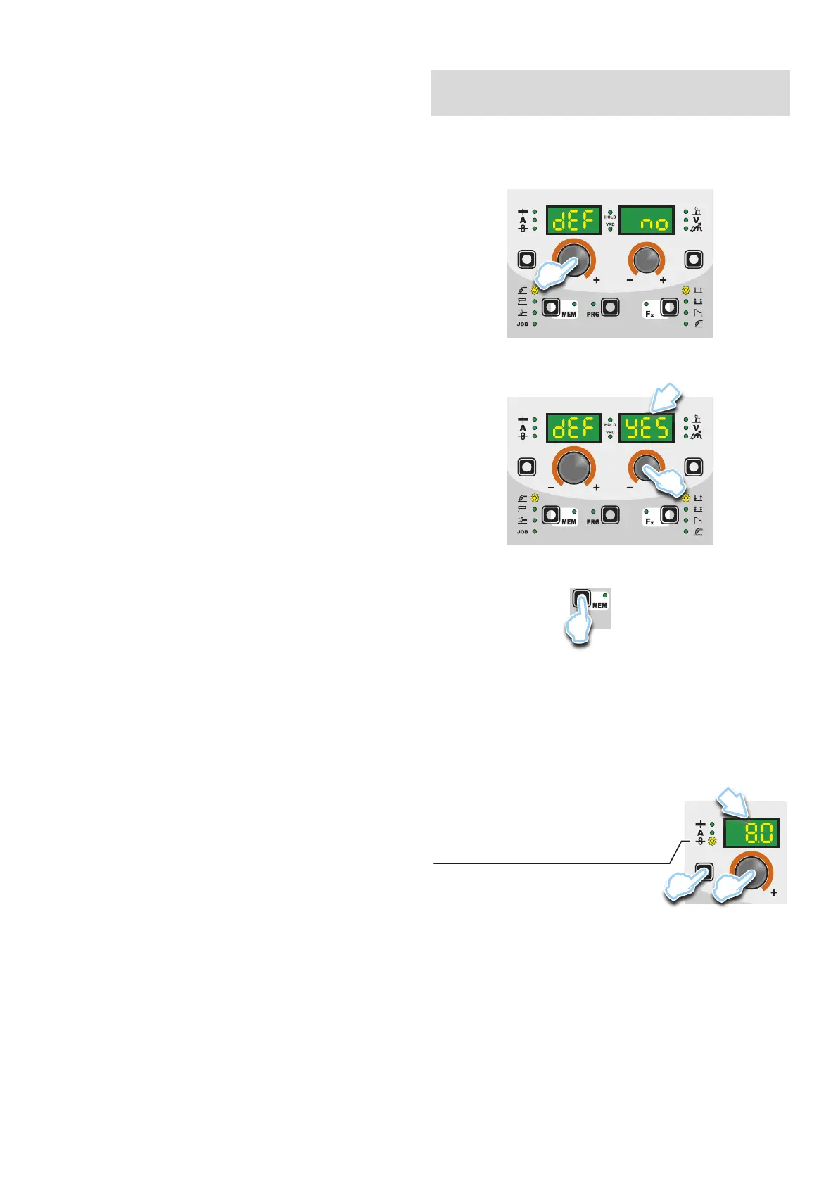
■ PROGRAM DEFAULT (dEF)
WARNING: If carried out, this operation resets the program
in use to the factory default settings.
To carry out the reset of the settings / parameters, proceed in the
following manner:
•
Rotate the ENCODER - A (E1) knob until both the displays read
dEF no (see figure).
E1
•
Rotate the ENCODER - V knob (E2) until the PARAMETERS
DISPLAY - V screen (D2) reads YES.
D2
E2
•
Hold the SAVE “MEM” key (T2) down for at least 2 consecu-
tive seconds.
T2
T ≥ 2 s
•
The program in use has now been completed successfully. To
confirmation the above, the control panel of the welder performs
a short operation of MACHINE CHECK (all of the LED stay lit
simultaneously so as to verify their actual operation), the gen-
erator itself starts, having memorised the new settings and is
again ready to weld.
4 - PRE-SETTING
Before welding it is possible to set the following parameters:
D1
T1
E1
WIRE SPEED
Example: WIRE SPEED
Press the PARAMETER SELECTION - A key (T1) until the LED
that corresponds to the WIRE SPEED switches on. Turn the EN-
CODER - A knob (E1) to change the value shown on the PARAM-
ETER DISPLAY - A screen (D1).