7
To carry out the reset of the settings / parameters, proceed in the
following manner:
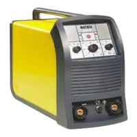
1) Rotate the ENCODER - A (E1) knob until both the displays
read FAC no (see figure).
E1
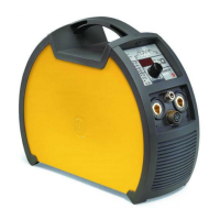
2) Rotate the ENCODER - V knob (E2) until the PARAMETERS
DISPLAY - V screen (D2) readsYES.
D2
E2
3) Hold the SAVE “MEM” key (T2) down for at least 2 consecu-
tive seconds.
T2
T ≥ 2 s
4) At this stage the total reset or factory default procedure has
been completed successfully (the parameters have been tak-
en back to the factory values and any JOBS saved have been
deleted). To confirmation the above, the control panel of the
welder performs a short operation of MACHINE CHECK (all
of the LED stay lit simultaneously so as to verify their actual
operation), the generator itself starts, having memorised the
new settings and is again ready to weld.
Menu SPECIAL FUNCTIONS
From the SEtUP menu, push the PRG key (T5) for more than 3
seconds to access the SPECIAL FUNCTIONS menu, which pro-
vides access to additional functions that can only be managed
by an expert, responsible operator. The two displays (D1-D2) will
read SPC FnC.
D1 D2
T5
T ≥ 3 s
SAFETY CALIBRATION CODE (SCC)
ATTENTION: This operation, if carryed on, optimizes the effi-
ciency of the welding circuit (only in MIG welding processes).
To set the length of the welding circuit (adjustable from 1 to 100
m) follow this procedure:
•
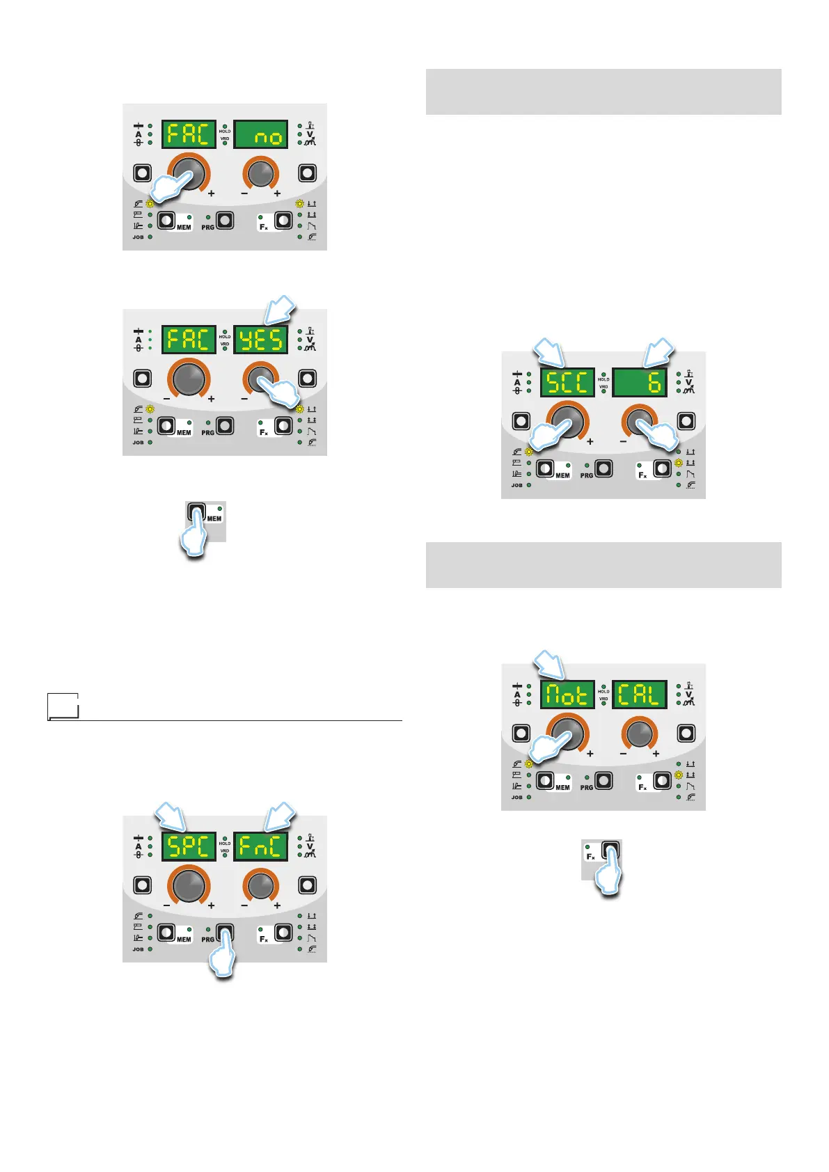
Rotate the ENCODER knob - A (E1) until obtaining on the PA-
RAMETER DISPLAY screen - A (D1) and the writing SCC.
• Rotate the ENCODER knob - V (E2) until obtaining on the PA-
RAMETER DISPLAY screen - V (D2) the desired number.
CAUTION: The operation does not require confirmation!
CAUTION: The data inserted is valid for all the MIG welding pro-
cesses.
Example:
Length of cable mass 3 m.
Length of welding torch cable 3 m.
The overall length of the welding circuit is 6 m (6 is the number that
will therefore be inserted).
D1 D2
E2E1
MOTOR CALIBRATION (Mot CAL)
ATTENTION: This procedure allows you to calibrate the wire
speed (only in MIG welding processes).
Proceed as follows:
•
Rotate the ENCODER - A (E1) knob until the PARAMETER DIS-
PLAY - A (D1) screen reads Mot CAL.
D1
E1
• To open the CALIBRATION menu, push the PRG key (T3).
T3
• The procedure of calibration is carried out in 3 different phases:
1. Calibration parameter SM1 (MINIMUM SPEED)
Push and release the torch button, and then wait for the
wire to stop automatically, and the End MiS message to ap-
pear. Measure (in cm) the dangling wire and insert the value
shown, in the software of the welder, by means of the rota-