9
2-SELECTIONOFWELDINGPROGRAMME
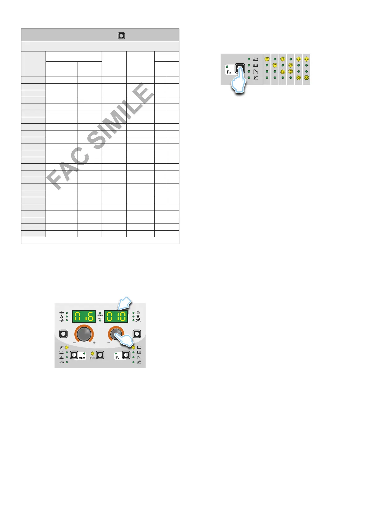
PROGRAM TABLE PRG
MIG-MAG-PULSE PROCESS
PROGRAM
NUMBER
MATERIAL
WIRE Ø
(mm)
GAS
DISPLAYS
TYPE CLASS MiG
PLS
dPL
000 Fe G3 Si-1 0.6 CO
2
●
001 Fe G3 Si-1 0.8 CO
2
●
002 Fe G3 Si-1 1.0 CO
2
●
010 Fe G3 Si-1 0.6 Ar/16-20%CO
2
●
011 Fe G3 Si-1 0.8 Ar/16-20%CO
2
● ●
012 Fe G3 Si-1 1.0 Ar/16-20%CO
2
● ●
015 Fe G3 Si-1 0,9 Ar/16-20%CO
2
● ●
051 Fe G3 Si-1 0.8 Ar/21-25%CO
2
●
055 Fe G3 Si-1 0.9 Ar/21-25%CO
2
●
195 Fe-rutil flux-cored E71T-GS 0.9 - ●
231 CrNi 308 G 19 9 LSI 0.8 Ar/2-3%CO
2
● ●
232 CrNi 308 G 19 9 LSI 1.0 Ar/2-3%CO
2
● ●
402 Al 99.9 S Al 1050 1.0 Ar ● ●
403 Al 99.9 S Al 1050 1.2 Ar ● ●
412 Al Mg 5 S Al 5356 1.0 Ar ● ●
413 Al Mg 5 S Al 5356 1.2 Ar ● ●
422 Al Si 5 S Al 4043A 1.0 Ar ● ●
423 Al Si 5 S Al 4043A 1.2 Ar ● ●
472 Al Si12 S Al 4047A 1.0 Ar ● ●
511 Cu Si 3 S CuSi3 0.8 Ar ● ●
512 Cu Si 3 S CuSi3 1.0 Ar ● ●
515 Cu Si 3 S CuSi3 0.9 Ar ● ●
911 Fe BD140 0.8 Ar/16-20%CO
2
● ●
951 Fe BD140 0.8 Ar/21-25%CO
2
●
PLS / dPL= Pulse version only
WARNING: This table is merely an example, the welding programs
can be updated and extended. See the table on the welding ma-
chine for the correct list of the programs available.
Select the welding PROGRAMME rotating ENCODER knob - V
(E2) until obtaining on the PARAMETER DISPLAY screen - V (D2)
the desired number.
D2
E2
3 - WELDING MODE SELECTION
Select the MODE of welding, pressing and releasing, even various
times if necessary, the WELDING MODE SELECTION key (T3)
until the corresponding LED lights up.
1 2 3 4 5 6
T3
1. TWO STROKE (2T)
2. FOUR STROKE (4T)
3. CRATER 2T
4. CRATER 4T
5. SPOT WELDING 2T
6. STITCH WELDING 2T
4 - SPECIAL FUNCTIONS “Fx” SELECTION
The SPECIAL FUNCTIONS “Fx” that are only available in the syn-
ergic MIG-MAG and pulsed / double pulsed MIG welding process
are shown below. For all the other explanations regarding this
menu make reference to the relative paragraph.
•
PRE GAS (PrG) - Provides an additional quantity of gas for a
defined time, before welding starts.
•
STARTING SPEED (StS) - Regulates the speed at which the
wire approaches the workpiece. The value indicated is a percent-
age variation in relation to the factory setting value.
• HOT START (Hot) - Regulates the current intensity for igniting
the welding arc. The value indicated is a percentage variation
in relation to the factory setting value.
•
CRATER START CURRENT (F08) - Sets the initial starting cur-
rent of the crater.
•
CRATER START TIME (F10) - This function defines the time
in which the current remains at the value of CRATER START
CURRENT.
•
CRATER START SLOPE (F11) - The time lapse for passing
from the CRATER START CURRENT level to the welding cur-
rent level.
•
CRATERENDSLOPE(F12)- Time required to go from the
welding current level to the “CRATER END CURRENT” level.
•
CRATER END CURRENT (F13) - Sets the final welding cur-
rent of the crater.
•
CRATER END TIME (F15) - This function defines the time in
which the current remains at the value of CRATER END CUR-
RENT.
• SPOT WELD TIME (F07) - The time during which spot welding
takes place after the arc is ignited, after which the arc is extin-
guished automatically.
•
STITCH WELD TIME (F05) - Time in which the welding in tracts
is performed after the ignition of the arch, after which the arch
switches off automatically.
•
STITCH WELD PAUSE (F06) - Time of pause between one
welding in tracts and another.
•
BURN BACK (bUb) - Regulates the length of the wire after weld-
ing. The value indicated is a percentage variation in relation to
the factory setting value. Higher numbers correspond to more
burning of the wire.
• POST GAS (PoG) - Provides an additional quantity of gas for a
defined time, after welding ends.
•
DUALPULSEDELTACURRENT(F23)- This function deter-
mines the positive or negative percentage variation in the peak
current, compared to the welding current set.
• DUALPULSEBALANCE(F25)- This function determines the
positive or negative percentage variation in the duration of the
peak current, compared to that of the welding current.
•
DUALPULSEFREQUENCY(F26)- This function determines
the variation in frequency (Hz) for double pulsed mode.