4
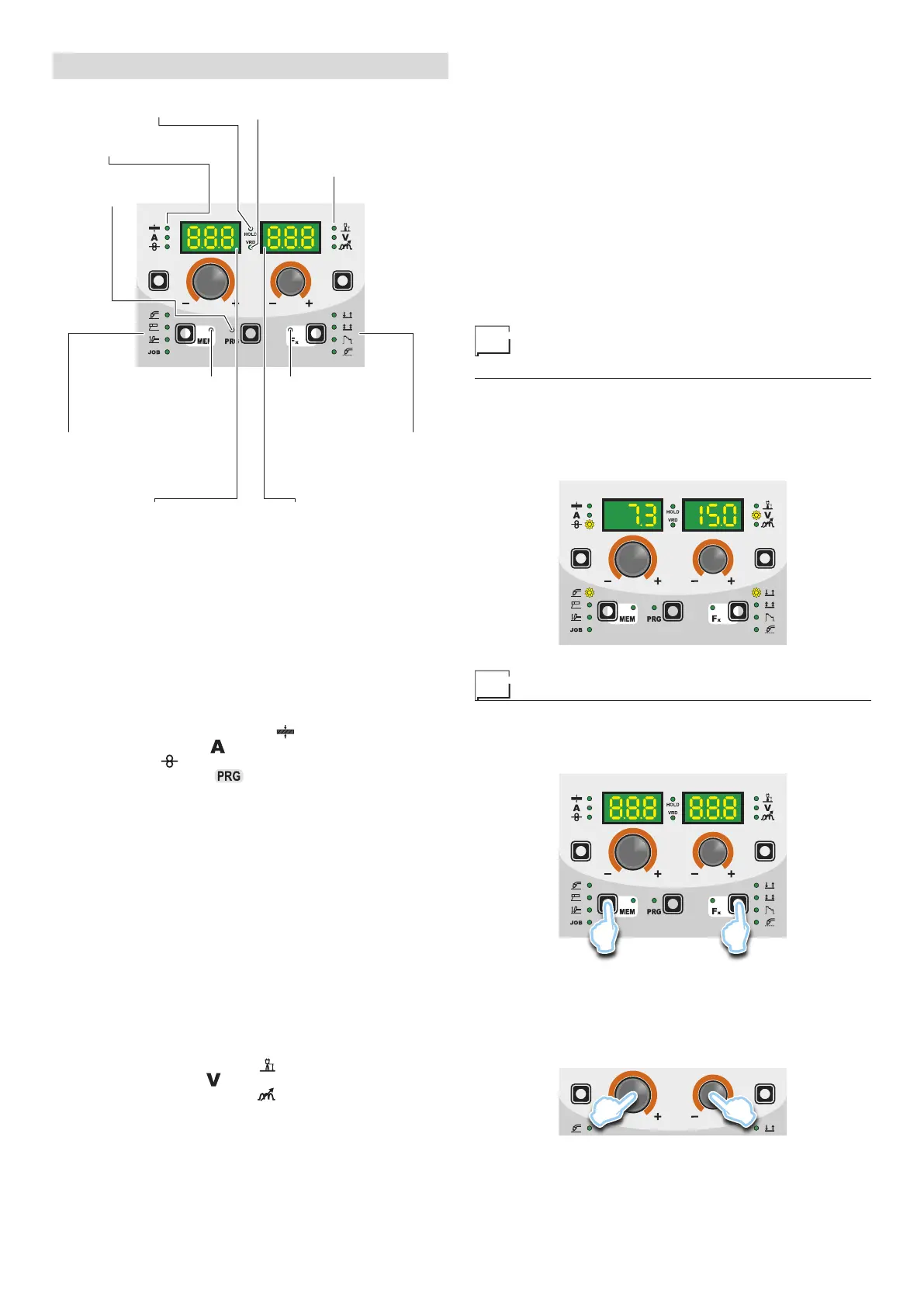
DISPLAY AND LED INDICATIONS
▪ VRD LED▪ HOLD FUNCTION LED
▪ PARAMETER
SELECTION LED - V
▪ PARAMETER
SELECTION LED - A
▪ PROGRAMME
SELECTION LED
▪ WELDING MODE
SELECTION LED
▪ Fx LED - SPECIAL
FUNCTIONS
▪ WELDING PROCESS
SELECTION LED
▪ JOB SAVING MEM LED
▪ PARAMETER DISPLAY screen - V▪ PARAMETER DISPLAY screen - A
■ PARAMETER SELECTION LED - A
When one of these LEDs is on it means that the corresponding
welding parameter has been selected.
■ PROGRAMME SELECTION LED
This LED will be lit only when the operator selects a welding pro-
cess (in which there welding programmes present) and the rela-
tive associated programme.
■ PARAMETER DISPLAY screen - A
This Display shows the values / numbers (set or measured) of the
following parameters (if active):
• THICKNESS OF WELDED ITEM (
).
• WELDING CURRENT (
).
• WIRE SPEED (
).
• WELDING PROGRAM (
).
■ HOLD FUNCTION LED
Flashing, it indicates that the values of the parameters views on
the PARAMETER DISPLAY - A and V are respectively the values
that are set or measured at the conclusion of the last welding. The
LED flashes for 15 seconds consecutively before turning itself off or
until the moment that the operator varies any parameter by means
of the use of the handles.
■ WELDING PROCESS SELECTION LED
When one of these LEDs is on it means that the corresponding
welding process has been selected.
■ PARAMETER SELECTION LED - V
When one of these LEDs is on it means that the corresponding
welding parameter has been selected.
■ PARAMETER DISPLAY screen - V
This Display shows the values / numbers (set or measured) of the
following parameters (if active):
• ARC LENGTH ADJUSTMENT (
).
• WELDING VOLTAGE (
).
• ELECTRONIC INDUCTANCE (
).
■ JOB SAVING MEM LED
Flashes while saving a JOB.
■ Fx LED - SPECIAL FUNCTIONS
Switched on when special Fx parameters are displayed.
■ VRD LED
The Voltage Reduction Device (VRD) is a safety device that re-
duces voltage. It prevents voltages forming on the output termi-
nals that may pose a danger to people.
Two-tone LED (off - red - green) indicates enabling of the VRD. In
the welding process:
• MIG MAG (Synergic and Manual) / JOB: the VRD device is not
managed and therefore the LED always will be off.
•
MMA: the operator can decide whether or not to activate the
VRD device (to activate the VRD device see the corresponding
paragraph) based on its necessities and therefore the LED will
be lit and will indicate the activation of the device.
•
TIG Lift: the VRD device is always inserted, independently from
the state of the JUMPER and therefore the LED always will be lit.
■ WELDING MODE SELECTION LED
When one or a combination of these LED is lit, it means that the
corresponding manner of welding has been selected.
Switching on the welding
machine and initial screen
At the switching on of the welder (press the switch, located on the
back panel, at the position I), the control performs a short operation
of MACHINE CHECK (all of the LED light themselves simultane-
ously so as to verify their actual operation), and the panel display
the INITIAL SCREEN (see the demonstrative figure), after which
the operator can begin to work.
Viewing the software version installed
1) When the welding machine is working hold down the WELD-
ING PROCESS SELECTION key (T2) and WELDING MODE
SELECTION key (T3) together for about 2 consecutive sec-
onds.
T2 T3
2) On both displays appears a running string that indicates the
VERSION OF THE SOFTWARE installed on the welder.
The rotation of one of the two ENCODER Knobs - A (E1) or
V (E2) by the operator during the display of the string version
software provokes the block (for 1 second), on both the dis-
plays, of the movement of the string itself.
E2E1