16
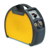
7 - ACTIVATING THE VRD DEVICE
The Voltage Reduction Device (VRD) is a safety device that reduc-
es voltage. It prevents voltages forming on the output terminals that
may pose a danger to people. The factory settings do NOT set out
an active welding device during electrode welding.
If the operator wishes to weld in MMA using the VRD device (which
must be done with the welding machine switched off), they must:
1) Use a suitable screwdriver to unscrew the 4 screws that fix
the control panel to the welding machine.
2) Remove the “VRD” JUMPER on the DIGITAL INTERFACE
PCB (Fig. B).
3) Use a suitable screwdriver to tighten the 4 screws that fix the
control panel to the welding machine.
4) Start the welder by pressing the switch, located on the back
panel, at the position I.
After switching on, but with the machine at rest, the control panel
will show the VRD LED on in the colour GREEN and this means
that the device is active.
During the welding phase, this LED becomes RED, which however
does not indicate a malfunctioning of the welder but the fact that
the VRD device is in function and, at the conclusion of the welding
operation, the tension will be reduced within a maximum greatest
time of 0.3 seconds.
TIG with “Lift” striking
Start the welder by pressing the switch, located on the back pan-
el, at the position I.
1 - WELDING PROCESS SELECTION
Select the TIG PROCESS of welding with “Lift” type starter for
welding without high frequency, pressing and releasing, also more
times if necessary, the WELDING PROCESS SELECTION key
(T2) until the corresponding LED lights.
T2
2-SPECIALFUNCTIONS“Fx”SELECTION
ADJUSTABLE FUNCTIONS “Fx” Fx > 3s
FUNCTION DISPLAY
SETTINGS RANGE
FACTORY RANGE
TIG process
UP SLOPE F29 0.0s (0.0 ÷ 20.0)s
DOWN SLOPE F30 2.0s (0.0 ÷ 20.0)s
SWS VOLTAGE LIMIT F31 0 -30 ÷ 30
PROGRAM DEFAULT dEF no no - YES
The SPECIAL FUNCTIONS “Fx” that are only available in the
TIGLift welding process are shown below. For all the other expla-
nations regarding this menu make reference to the relative par-
agraph.
•
UPSLOPE(F29)- Allows the joining of the WELDING CUR-
RENT to the INITIAL CURRENT.
•
DOWN SLOPE (F30) - Allows the joining of the WELDING CUR-
RENT to the FINAL CURRENT.
•
SWS VOLTAGE LIMIT (F31) - Regulates the voltage level for
automatic automatic extinguishing.
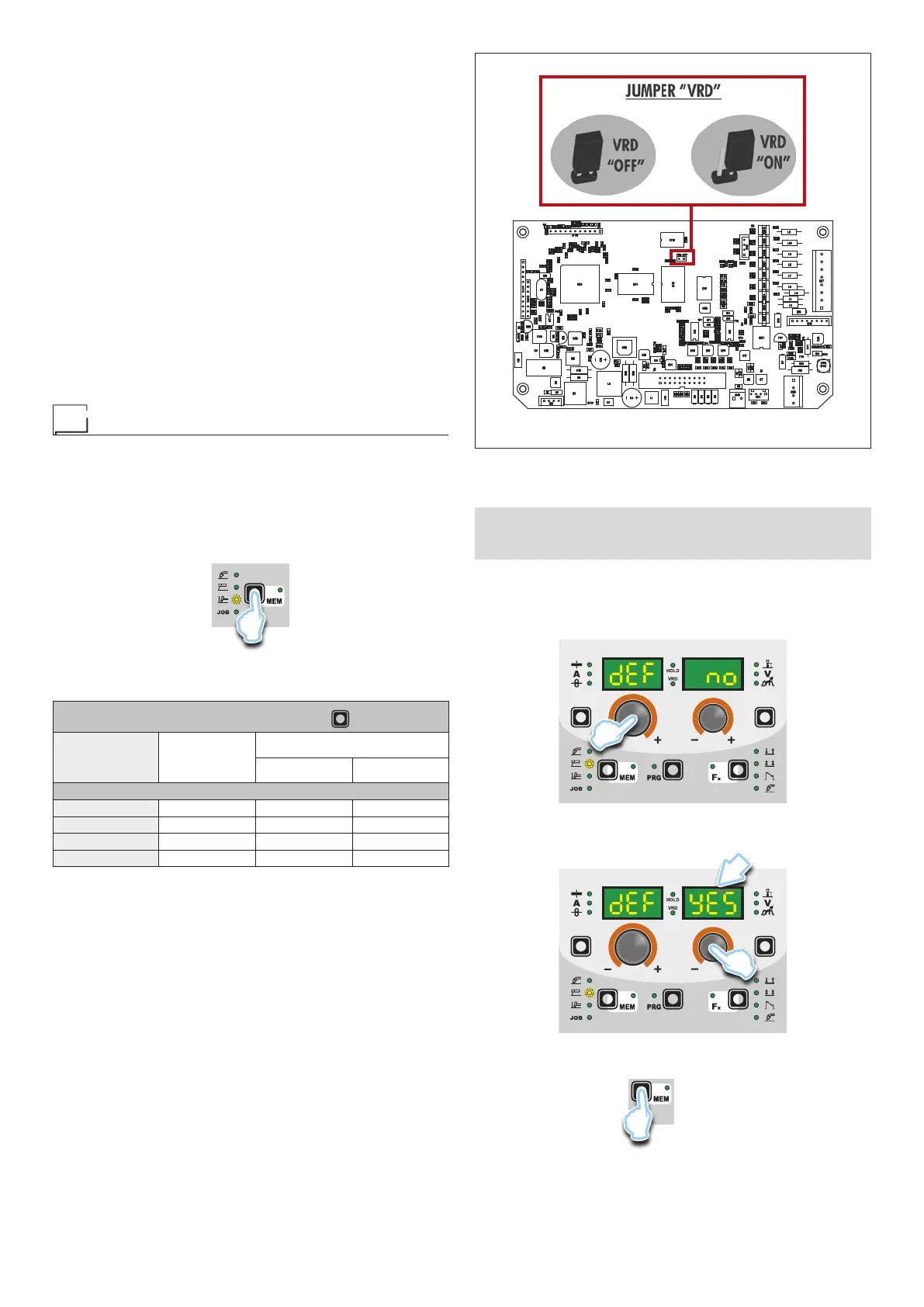
■ PROGRAM DEFAULT (dEF)
WARNING: If carried out, this operation resets the program
in use to the factory default settings.
To carry out the reset of the settings / parameters, proceed in the
following manner:
•
Rotate the ENCODER - A (E1) knob until both the displays read
dEF no (see figure).
E1
•
Rotate the ENCODER - V knob (E2) until the PARAMETERS
DISPLAY - V screen (D2) reads YES.
D2
E2
•
Hold the SAVE “MEM” key (T2) down for at least 2 consecu-
tive seconds.
T2
T ≥ 2 s
FIG. B