Ⅱ
Ⅱ-26
A
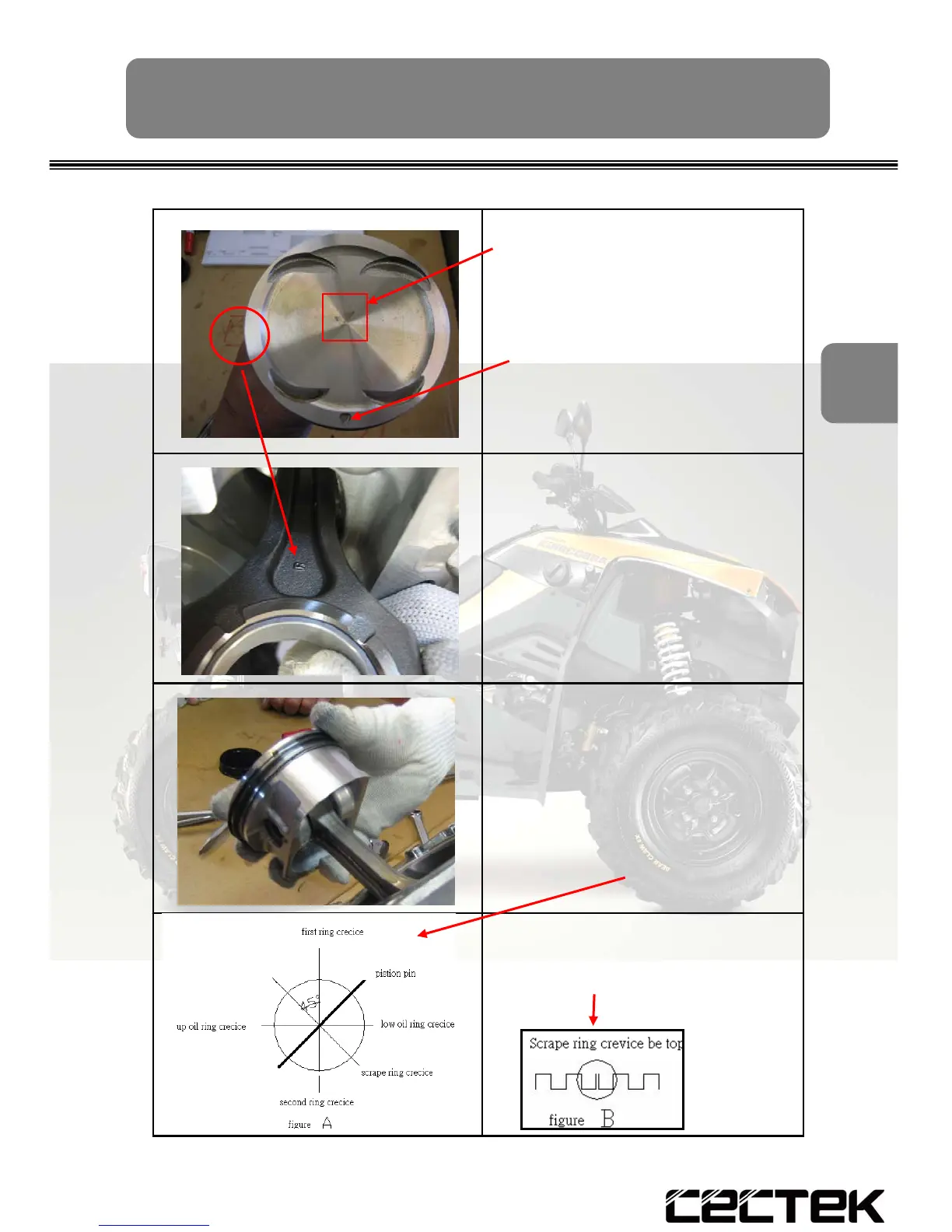
5.The piston size mark on top
( A or B )
6.Confirm:when you face
the piston , the piston (4,5)
exhaust mark is in the
down side
7.Confirm:
the connecting rod
(1) right side mark R is same
side of piston
8.Install one clip (3) into the
piston clip groove firmly
9.Install pin (2) into pin groove
10.Install the clip (3) into the
other side groove to stop
the pin (2)
11.Then sequentially install
parts (8) , (7) , (6) , the
crevice position of each
ring as figure A shows
12.The opening of ring (8) of
spacer shall be upward as
figure B shows
ENGINE - Assembly